My first two active speaker projects used Hypex Fusion amps, which have built-in DSP. I think the Hypex amps are excellent, but I was looking at less expensive options.
Originally, I expected this Twin-8's project to be an inexpensive portable speaker. However, it morphed into a fairly heavy speaker that was complicated to build. Given the complexity of the construction, it seemed foolish to use inexpensive lower-performance drivers, so I increased my driver budget to middle-range drivers. Once I did that, I did not want to risk the performance by using the Wondom JAB5. It has no established reputation, and the reliability is unknown at this point. The speaker cabinet has to be designed around the electronics, so if I became unhappy with the JAB5, it would be very difficult to retrofit a different electronics package. With that in mind, a Hypex FA-123 seemed a lower risk approach, although somewhat more expensive.
j.
I will be bringing this speaker to the InDIYana event April 28-29
Hi Jim. I’ve learned a lot from brown your projects.
Another spacing question: how did you design the distance between the 2 8“ woofers and the mid? Also, what factored into the spacing of the 2 8” woofers from each other? And was woofer floor reflections a factor in your decision?
One way would be to shoot for a .25 WL spacing between woofer and mid. At 300hz that’s ~11.25”, which can be accomplished by a single larger woofer (but you lose the slim baffle width or dynamics w/ only 1 woofer). Or 2 smaller woofers placed vertically, physically close together, taking the distance from the center of the 2 woofers to the mid.
Then there’s the 1.25 WL spacing approach, as with the mid/tweeter, but at 300hz xo that’s too big a spacing.
But then there are the floor reflections. At the longer wavelengths 300hz and below, the woofers can “see” their reflections and couple the same way as adding additional drivers. Floor gain with the woofer down by the floor can also be thought of adding a woofer, getting that 6db gain.
So then I get confused about where the center is. If I have 2 woofers close to the floor, is the center between the 2 woofers and the mid, or is it really at the floor, because I have 4 woofers, counting the reflection. If so, then really can get around 1 WL spacing between woofers and mid if you have enough woofers to reach to the floor, creating a woofer line array.
I’m not sure if that’s the right line of thinking, so I’m curious what your thought process is when deciding woofer spacing.
Hi Jim. I’ve learned a lot from brown your projects.
Another spacing question: how did you design the distance between the 2 8“ woofers and the mid? Also, what factored into the spacing of the 2 8” woofers from each other? And was woofer floor reflections a factor in your decision?
This may be surprising, but I did not do a lot of analysis on the woofer spacing or positioning. As you point out, the floor is going to be a contributor, and when we get down to 200 Hz we are in the Schroeder frequency where room modes dominate.
11.25 inch spacing would be 1/4 wavelength at 300 Hz, and that is approximately the distance between the two 8" woofers. This means that they radiate as a single oval-shaped driver. The distance from the center of the mid to the center of the "oval" woofer is about 16", which is about 1/3 wavelength at 300 Hz. This is not ideal, but 1/3 wavelength spacing is only slightly less optimal than 1/4 wavelength spacing. The simulations aren't too bad, and there is a bit of vertical directivity which is usually a good thing.
The above rationale is fairly simple, but going beyond that simple line of thinking into something more sophisticated (floor and room boundaries) becomes very complicated, very fast. So basically, I did not over analyze the situation. I looked at the spacing in a number of successful commercial and DIY dual-woofer-towers, and I just went with what seems to work well.
So then I get confused about where the center is. If I have 2 woofers close to the floor, is the center between the 2 woofers and the mid, or is it really at the floor, because I have 4 woofers, counting the reflection.
That is a good question, and I do not know the answer. My philosophy has always been to design a speaker which is anechoically flat, even though it is no longer "flat" when put into a real room. This is based on F. Toole's findings about what sounded best to most listeners.
Apparently four closely spaced drivers in a vertical array in free space is acoustically the same as two at the floor, ergo the floor line is the centerline. Never actually tested it, but seems reasonable since a line array that's at least ~71% of a room height performs as if the drivers went full height.
https://archive.org/details/HowToBuildSpeakerEnclosuresByAlexixBadmaieffDonDavis/page/n25/mode/2up
https://archive.org/details/HowToBuildSpeakerEnclosuresByAlexixBadmaieffDonDavis/page/n27/mode/2up
https://archive.org/details/HowToBuildSpeakerEnclosuresByAlexixBadmaieffDonDavis/page/n25/mode/2up
https://archive.org/details/HowToBuildSpeakerEnclosuresByAlexixBadmaieffDonDavis/page/n27/mode/2up
That all makes sense. Yes, I noticed your woofers were about 1/4WL from each other and about 1/3WL from the mid. Seemed reasonable to me and I figured you modeled it as well so of course it end up working well. Yes, I’ve also noticed that successful towers can really have anything from dual woofers to 3 or 4 all the way down, so it must not matter that much in practice.The above rationale is fairly simple, but going beyond that simple line of thinking into something more sophisticated (floor and room boundaries) becomes very complicated, very fast. So basically, I did not over analyze the situation. I looked at the spacing in a number of successful commercial and DIY dual-woofer-towers, and I just went with what seems to work well.
I agree with you and Floyd Toole. And yet, some designs take advantage of reflections, such as straight line arrays, ground plane CBTs (F. Toole talks about this example in his book, and suggest using the ceiling as a reflection plane for surrounds), arrayable horns such as corner horns, etc.My philosophy has always been to design a speaker which is anechoically flat, even though it is no longer "flat" when put into a real room. This is based on F. Toole's findings about what sounded best to most listeners.
But I’m not sure if using the floor reflection is a design goal for any of the successful tower designs. It could be it sort of looks that way (for example the Salon 2 and PerformaBe f328Be have 3 8’s down to the floor), but the real goal is to add more bass within the specified baffle width.
I agree that it has to be true that the floor, the mirror plane, is acoustic center of closely spaced woofers that are also close enough to the floor. I think this should be easily enough to model in free space by simply doubling the woofers with mirror image spacing.Apparently four closely spaced drivers in a vertical array in free space is acoustically the same as two at the floor, ergo the floor line is the centerline. Never actually tested it, but seems reasonable since a line array that's at least ~71% of a room height performs as if the drivers went full height.
https://archive.org/details/HowToBuildSpeakerEnclosuresByAlexixBadmaieffDonDavis/page/n25/mode/2up
https://archive.org/details/HowToBuildSpeakerEnclosuresByAlexixBadmaieffDonDavis/page/n27/mode/2up
Closely spaced woofers makes a small line array. With a tower, the line of woofers could easily be 1 meter high, giving an effectively 2 meter line array. With line arrays, vertical pattern control is proportional to the length, and every doubling of length gives another octave lower of pattern control. The reflection does contribute a free doubling. I’m not sure if it makes sense to try to make a ground plane array out of the woofers on purpose, though. There may be drawbacks.
That is a really cool book, by the way. Love the old pictures and explanations. Reading through it now!
There is a lot to consider and the idea of designing solely based on simple boundary conditions will come unstuck in most real rooms. Outside on a hard and reflective surface far away from other surfaces to reflect there will be a nice 6dB increase from the acoustic mirror image. Bring the same thing inside and the certainty goes out of the window. Is the floor concrete, is it timber suspended, are the walls concrete or timber framed plaster? These will all have very different responses in the modal region even though they might appear to be the same visually.
Here are links to look at that might give you some idea of how the drivers can couple in multiples and how they may interact with the boundaries.
https://www.diyaudio.com/community/threads/modular-active-3-way-work-in-progress.326926/post-5927729
https://www.diyaudio.com/community/threads/a-3-way-design-study.376620/post-6845315
http://www.troelsgravesen.dk/BOOKSHELF-1/RoyAllison.pdf
https://www.htguide.com/forum/missi...9-2021-2023-isiris-update?p=836660#post836660
Thanks Fluid... This is what I meant when I said that "...going beyond that simple line of thinking into something more sophisticated (floor and room boundaries) becomes very complicated, very fast. "There is a lot to consider and the idea of designing solely based on simple boundary conditions will come unstuck in most real rooms.
When I laid out the baffle design, I reviewed the @DonVK material on dual woofers, and any other info on DIY.com that I could find. I concluded that a particular twin woofer layout might be beneficial to a particular room geometry and listening position, but it would be very difficult for me to determine that in advance, and that benefit might disappear in a different room.
@fluid , thanks so much for taking the time to gather all of those links. I will go through all of them!Here are links to look at that might give you some idea of how the drivers can couple in multiples and how they may interact with the boundaries.
So far, in reading through the first several pages of @DonVK ’s 3d sims, it does indeed look like a longer array of smaller woofers models better (4 6.5” to the ground vs 2 8’s). Then he built it and confirmed it both measures and sounds better. The measurements show a more even vertical dispersion.
Carpet, etc should not have much of an effect on the woofer reflection effect because at the low hundreds of hz and below you’d need massively thick absorbers. DB Keele likes to point out in his ground plane array demos that it still works because it only effects the very highest frequencies, and his ground plane CBTs even included the tweeters all the way to the ground.
DonVK’s thread is very interesting for me, because I was thinking of building something similar. Something like a dome midrange 3 way with the new Bliesma domes + tweeter. If the crossover to woofers is 500hz, then I’d be looking at around 6.5” woofers to keep them .25WL from each other—the, exact size DonVK chose for his 4 woofer array.
I’ll keep reading. Thanks again!
There are proponents who say that a larger flat baffle area around the tweeter delays the diffraction events, increasing their angle to the listener and rearranging their polars.The current "best practice" for a non-waveguide tweeter is to (1) make the baffle around the tweeter as small as possible,
What is not often said is that it allows clean establishment of more of the overall radiation, meaning that less of it sees the edge and gets diffracted. In addition you gain control for it to be more narrow. As there is some frequency dependence, there are factors to analyse case by case.
Here is an example of the narrower baffle having greater higher order mode coverage.
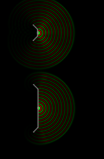
Hi, if you swap in line source in the ripple tank there is not much difference between the two 😉 Or if you reduce frequency the small baffle clears up and the bigger one shows the exact same pattern.
Frequency dependence is due to size of the baffle, and size of the transducer, and it all relates to wavelength. If a tweeter is on minimal baffle, any secondary sound source that happens at the edge and radiates direction of listener is now at relatively high frequency. When you increase size of the baffle keeping the same direct radiating tweeter there, what you do is increase both delay to the edge (distance) and increase bandwidth of frequencies that makes the secondary sound source at the edge. This makes the secondary sound source lower in frequency, from lower frequency to all the way up to where it was on the small baffle because the upper end of secondary sound source is defined by the transducer. When it beams, less sound towards edge.
What is more audible is not clear as I haven't done or seen a test. Intuitively small baffle diffraction is less audible, example:
Extreme cases for direct radiating tweeter on a big and small baffle would be roughly: on a relatively big baffle secondary sound source for a tweeter happens at the edge for its whole frequency bandwidth roughly 1-10kHz and is perhaps some ~15cm, or ~0.5ms late on average, a 30cm diameter baffle so ~1kHz is affected. On a minimal/no-baffle secondary sound of the edge it might come perhaps 1.5cm, or 0.05ms later and only at high frequency, 3cm diameter so about ~10kHz. Basically the secondary sound source bandwidth shrank to none, and delay reduced to very short.
Basically, distance from edge of the transducer itself to ear is roughly the same as distance from edge to ear. I'm thinking the edge is now indifferent to the transducer itself, not a secondary sound source anymore. For a cone speaker this is frequency where the cone breakup happens and all that, response gets nasty even on a infinite baffle.
All this is clearly seen on all the sims you can perform. Only question left is what is more audible, or whether any of it matters domestic listening levels.
Last edited:
AllenB I think I see your point, when the edge is far enough the pristine direct sound has made the audio impression before the secondary sound of the edge arrives. I'm not sure how brain processes the stuff it and what is the time interval required and so on.
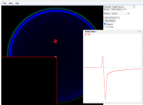
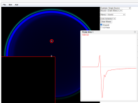
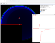
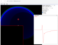
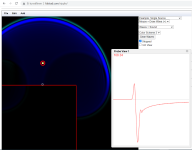
Here is ripple tank sim , when the edge is close, the impulse itself is changed, unless its very close, or very far.
Knowing audibility of the stuff would be the key.
Here is ripple tank sim , when the edge is close, the impulse itself is changed, unless its very close, or very far.


Knowing audibility of the stuff would be the key.
A regular tweeter faceplate is flat, and more than a quarter wavelength to the edge above 1,700Hz. This means the direction has begun to be defined and anything else is going to be a change. Also the levels are strong at that distance.
Precedence effect has some bearing but if I might ask a rhetorical question when you design your waveguides, do you also like to put your diffraction within the first millisecond where you have the option to leave it until later?
Precedence effect has some bearing but if I might ask a rhetorical question when you design your waveguides, do you also like to put your diffraction within the first millisecond where you have the option to leave it until later?
Very amusing 😉if you swap in line source in the ripple tank there is not much difference between the two 😉
Yeah the typical ~10cm tweeter faceplates dictate there will be diffraction unless huge roundovers / slants starting immediately past that.
I don't know what time interval is needed so I just reduce diffraction secondary sound source in amplitude, roundovers, all the way around. One could do past 1ms edge distance, but its painful to build and comes with resonance issues and stuff like that, practical issues. Impossible (for me) to have at home, unless in-wall.
Perhaps even more audible than the diffraction is reflection from the wall behind speakers, which is also function of baffle (object) size.
Thinking about it, any structure around a transducer is a waveguide so better to make best of it 🙂
- Home
- Loudspeakers
- Multi-Way
- New Project - tower 3-way with twin 8s