the ideal sim looks cool!When I simulated this cabinet design using idealized drivers, the response looks pretty good. "Diffraction is destiny", and if the cabinet does not work with idealized drivers, it will probably not work with real drivers. I really appreciate the power of VituixCad because it allows me to construct a "final" cabinet without having to make several iterations of prototype cabinets. The actual filters I end up with after measuring and simulating my real drivers will no doubt be different from this idealized model, but that does not detract from the usefulness of this simulation. It gives me confidence that the concept is viable and feasible.
j.
+1 for the vcad love.
Ever load the manufacturer/hificompass data into the baffle sim? I get that the ideal version should be the starting point.
1.2X the WL of the XO?Have I missed something, or isn't the CTC between the tweeter and midrange pretty big?
Who wrote where that 1,4-1,7 x WL is best apart from <0,25 x WL?Have I missed something, or isn't the CTC between the tweeter and midrange pretty big?
Great watching this build progress awesome work Jim, have you looked at the Dayton Audio PS65LP-4? 122cm2, Fs 67, sens 99dB, Xmax of 4mm, the 1 downside the cone is poly, the FR looks good probably quite tamable up to 6k.I agree. I would like to see a driver with an Sd of ~ 100 cm^2, an Fs of 60 Hz, sensitivity of ~ 92 dB/2.83V, an Xmax of 3 mm 0-pk, and a cone material of either aluminum or composite, with a first mode resonance above 6 kHz.
Then I would like to see smaller versions with an Sd of ~ 70 cm^2 and 50 cm^2, with proportionately higher Fs.
j.
Regarding the spacing of the mid and tweeter: My earlier projects had the tweeter and mid placed as close together as possible. I did not use simulation to help position the drivers on the baffle, I simply vertically aligned them as close together as possible, and then made the cabinet as low diffraction as possible. I ended up with a Center To Center (CTC) distance of about 0.75 x crossover wavelength. This led to a -3 dB dip in my power response at the crossover.
For this project, I wanted to use simulation from the very beginning and focus on managing the DI. The current "best practice" for a non-waveguide tweeter is to (1) make the baffle around the tweeter as small as possible, (2) space the mid and tweeter at a CTC distance of 1.2 x crossover wavelength. I did a lot of simulation over the last 9 months to convince myself that this is true. The 1.2 x wavelength looks odd to me, and I wanted to believe that I could space them closer together... I finally realized that a close spacing was not going to work. Thanks goes to Kimmo and Fluid for pushing me in the correct direction.
I do not know the exact details of the final crossover, but I believe the crossover frequency will be between 1.8k and 2.1k. That would make the CTC distance range from 229 mm to 196 mm, with an average of 213 mm. I convert my dimensions to inches before I cut (because I am an American and we like to do things the hard way), so rounding to the nearest 1/8 inch I get a CTC distance of 8.25 inch, or 209 mm.
j.
No clue 🤷 I read that some freedom can be applied, but I can't understand why, since usually getting around one compromise, easily make you enter another .Who wrote where that 1,4-1,7 x WL is best apart from <0,25 x WL?
Jim, did you keep the results of the closer spacing? Would be nice to compare the two, so we can see where the difference came from.
How do you calculate distance between 2x8 (bass unit) and midrange ?
And the distance between two bass units ? ( keep them as close as possible? )
Could you give me an example if crossover is at 550hz between midrange and 2x bass units.
Thanks
And the distance between two bass units ? ( keep them as close as possible? )
Could you give me an example if crossover is at 550hz between midrange and 2x bass units.
Thanks
the ideal sim looks cool!
+1 for the vcad love.
Ever load the manufacturer/hificompass data into the baffle sim? I get that the ideal version should be the starting point.
1.2X the WL of the XO?
I did that step back in post #12 for a different baffle configuration. It compared so well to the ideal driver simulation of that baffle that I decided to skip that step at this stage.
I should mention that Headshake was first person to push me toward the VituixCad universe... Thanks for that!
j.
The wavelengths involved the typical mid-woofer crossover are so large eg, 60cm for 550Hz, to 1m for 350Hz that they don’t need to be right next to the midrange.
And thus the advantages of using dual woofers (apart from the SPL gain (+6dB for sources in parallel)) is that you can move the 2 woofers separately up/down and thus model/adjust for the floor bounce interaction below the woofers, and the midrange interaction above the woofers; with your intended W-M crossover frequency.
the use case is specific to your desired design axis and your selected woofer size, I could not find a one-case-fits-all placement. Or perhaps I wasn’t patient long enough.
Looking forward to hear from others have found from the modelling to the actual measurements to verification stages.
Jim, did you keep the results of the closer spacing? Would be nice to compare the two, so we can see where the difference came from.
I did not run simulations of mid-tweeter spacing with this particular baffle design. However, there is another thread where I worked through a lot of simulations to arrive at the "winning combination" for mid-tweeter baffle shape. Post#193 is where I discuss my findings...
https://www.diyaudio.com/community/...ith-ideal-drivers.380658/page-10#post-6977833
Recent reviews of 3-way towers with double woofers - back to basics!
https://www.audioholics.com/tower-speaker-reviews/heco-aurora-1000/conclusion
https://audio.com.pl/testy/stereo/kolumny-glosnikowe/3506-sonus-faber-lumina-v
https://audio.com.pl/testy/stereo/kolumny-glosnikowe/3504-canton-townus-90
https://audio.com.pl/testy/stereo/kolumny-glosnikowe/3498-linn-products-majik-140
https://www.stereophile.com/content/monitor-audio-silver-500-7g-loudspeaker
https://www.soundstagenetwork.com/i...&catid=77:loudspeaker-measurements&Itemid=153
https://www.stereophile.com/content/bowers-wilkins-diamond-series-804-d4-loudspeaker
https://www.stereophile.com/content/stenheim-alumine-three-loudspeaker
I fail to see any logic between baffle dimensions/edge contour and measured performance (B&W with minimal baffle has most ragged response...)
Check put the normalized horizontal plots. B&W is smooth as butter diffraction wise up to ~6kHz. It is hard to see from the pictures if the tweeter is with roundover. Perhaps that grill makes it. Response narrows past 2kHz because the mid driver is too big and crossover frequency so high.
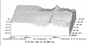
In comparison the last link Stenheim, mid driver diffraction seen all the way from 1khz up until its response narrows until tweeter kicks in and makes its statement 🙂
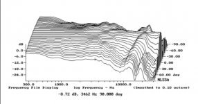
Here is the monitor audio silver, diffraction nicely all the way from mids to top.
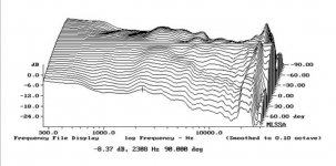
Main diffraction hump shows as smooth narrowing, first on axis diffraction dip after that makes the nice off axis ridge (b&w). Offset drivers make the bumps here and there instead of ridge (stenheim).
If there wasn't any diffraction the lines on these graphs would be much smoother and not much ripple. Unless some nasty cone breakup but those sound bad and are usually suppressed so a lot of the wiggle in these graphs is just diffraction. Or narrowing response of some mid woofers.

In comparison the last link Stenheim, mid driver diffraction seen all the way from 1khz up until its response narrows until tweeter kicks in and makes its statement 🙂

Here is the monitor audio silver, diffraction nicely all the way from mids to top.

Main diffraction hump shows as smooth narrowing, first on axis diffraction dip after that makes the nice off axis ridge (b&w). Offset drivers make the bumps here and there instead of ridge (stenheim).
If there wasn't any diffraction the lines on these graphs would be much smoother and not much ripple. Unless some nasty cone breakup but those sound bad and are usually suppressed so a lot of the wiggle in these graphs is just diffraction. Or narrowing response of some mid woofers.
Last edited:
A quick off-topic side bar about B&W... What happened to them? 25 - 35 years ago they made speakers which were at the top level of performance. In the early 1990's I heard a 801Matrix that super impressed me. When we look at the measured performance of the 801 Matrix-2 from 1995 https://www.stereophile.com/floorloudspeakers/506/index.html it is significantly better than their current offerings. ?
After John Bowers died Laurence Dickie was head designer for B&W. Laurence was initially employed as amplifier designer because they were doing active speakers back in the 1980s. AFAIK Laurence is responsible for the matrix cabinets and exponential tapered tubes and Nautilus. After he left in 1997 to go Turbosound where he was for awhile before founding his own speaker company Vivid Audio, that's the one I'd buy if I was looking into B&W today.
A lot of their drivers are excellent, but crossovers and overall system design? errr.. not so much.
I don't know who was at the helm after Laurence left, I'll see if I can find out.
A lot of their drivers are excellent, but crossovers and overall system design? errr.. not so much.
I don't know who was at the helm after Laurence left, I'll see if I can find out.
Last edited:
Check put the normalized horizontal plots. B&W is smooth as butter diffraction wise up to ~6kHz. It is hard to see from the pictures if the tweeter is with roundover. Perhaps that grill makes it. Response narrows past 2kHz because the mid driver is too big and crossover frequency so high.
View attachment 1057193
In comparison the last link Stenheim, mid driver diffraction seen all the way from 1khz up until its response narrows until tweeter kicks in and makes its statement 🙂
View attachment 1057194
Here is the monitor audio silver, diffraction nicely all the way from mids to top.
View attachment 1057195
Main diffraction hump shows as smooth narrowing, first on axis diffraction dip after that makes the nice off axis ridge (b&w). Offset drivers make the bumps here and there instead of ridge (stenheim).
If there wasn't any diffraction the lines on these graphs would be much smoother and not much ripple. Unless some nasty cone breakup but those sound bad and are usually suppressed so a lot of the wiggle in these graphs is just diffraction. Or narrowing response of some mid woofers.
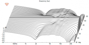
Played with VituixCAD and it can do close the same graphs as the Stereophile normalized horizontal graphs are. Attached is a VituixCAD project that can produce the images below. I urge anyone play with it to gain some insight how the speaker construct relates to various things on the graphs.
Here is ideal point source, this is the best that can be, straight lines. This is omni and all off-axis angles have same level. If it was narrower directivity but still constant directivity, the lines to off-axis angles were just lower in level but still straight.
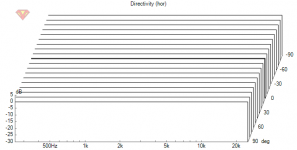
Below responses are ideal 1" and 8" transducers on ~minimal 20x40cm baffle made with VituixCAD diffraction tool.
Here is only the tweeter with and without 25mm corner radius on baffle. Response is about omni on low frequencies until baffle starts to narrow it, eventually the transducer beams as wavelengths get shorter than the diameter. Diffraction in between which almost cleans out with 25mm radius roundover on the baffle edge. The baffle is quite large for the tweeter and roundovers are needed to reduce diffraction.
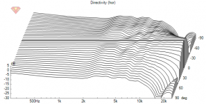
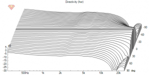
This is ideal 8" woofer on the same baffle without and with 25mm roundovers. Its minimal baffle for the woofer so not much effect to its response.
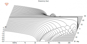
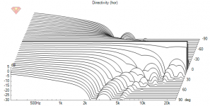
And here is the system with 3kHz LR12 crossover, with and without the roundovers:
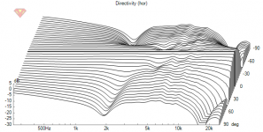
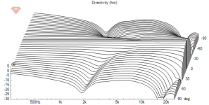
Yes its not too good of a system, 8" and 1" with 3kHz crossover, just something arbitrary to give more data whats what on the graphs.
Is there anything to learn? Yeah, do roundovers (and EQ) if you wanna make your graphs look better than in Stereophile! Pay attention to driver sizes and locations, structure, the construct.
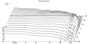
Note the graphs are Normalized to on-axis, meaning that the on-axis response is "EQd" perfectly flat to show off-axis angles response in comparison to that. Perhaps Juhazi observed from the graphs he linked on post #113 the B&W really has kind of wild on-axis response and came to conclusion minimal baffle didn't help. The ragged response is not due to diffraction though, except some on the tweeter but less than with the others, and could be EQ:d pretty nicely.
Here is simulation with real system measurements. Its not normalized but just EQ:d quite flat, the construct is made low diffraction without roundovers, basically its no baffle cardiodish with freestanding waveguide. Wouldn't be so nice without help of DSP, would have ragged on-axis response but normalized graph would look about the same as this. Btw there is two crossovers here, its a three way system.
Attachments
Last edited:
Here is a measurements of my 3 way,

The reason for this is not because I am a good designer, but because I followed Kimmo/VituixCAD's directions and took real measurements in 360 degrees BEFORE I started the crossover.
And before that I also simulated the baffle dimensions and driver positioning with VituixCAD diffraction modeller.
B&W's engineers are clever enough but my guess it that
a) they want to make the most of their soft cone FST, which admittedly extends out to 10KHz
b) they are probably using old processes, old tools.
Maybe bit of a) and a bit of b)
That is a darn high XO for an 8". Is that what the B&W is using? I ended up with a LR8 on the woofer around 2100hz to match to a 1".8" and 1" with 3kHz crossover,
Cool comparison!
DSP is just a tool. It is not its fault it is awesome.Wouldn't be so nice without help of DSP,
Your system must sound great!
...
B&W's engineers are clever enough but my guess it that
a) they want to make the most of their soft cone FST, which admittedly extends out to 10KHz
b) they are probably using old processes, old tools.
Maybe bit of a) and a bit of b)
Yeah and perhaps little bit of diffraction doesn't matter much, its very hard if not impossible to get rid of all 🙂
That is a darn high XO for an 8". Is that what the B&W is using? I ended up with a LR8 on the woofer around 2100hz to match to a 1".
Yeah probably not what B&W uses. This was just an example with arbitrary crossover point, I should have been more clear on that to avoid confusion. The response looks about the same with 2kHz xo, tunable in the attached project if you wish experiment with it. Few minute project to whip up from zero 🙂 I really like doing these, they teach so much being adjustable in real time. It takes few minutes to experiment and learn the stuff, but multiple hours to compose a post like that on the forum.
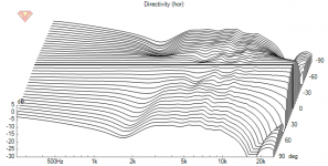
Hah yeah, I see no reason not to use one 🙂 I don't have expensive amplifier that would require passive speakers and can roll my own amplifier systems so multichannel is not too expensive or cumbersome, its gonna be tailor fit. Gonna be, because have had only mono system for many years 😀 Sounding good but I've got no idea about absolute quality, not much to compare to. I haven't visited Hifi shops in long time and don't have friends with good speakers so only reference is small town live events..DSP is just a tool. It is not its fault it is awesome.
Last edited:
- Home
- Loudspeakers
- Multi-Way
- New Project - tower 3-way with twin 8s