Potential issues untreated
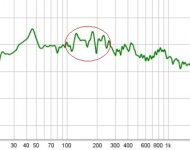
This is the frequency range where airborne resonances appear in an enclosure sized like yours, 440 litres. One would put the right amount of fibers until these disappear from the plots, especially impedance plots where they can be spotted easily.
This is the frequency range where airborne resonances appear in an enclosure sized like yours, 440 litres. One would put the right amount of fibers until these disappear from the plots, especially impedance plots where they can be spotted easily.
Attachments
Thank you Earl and Lojzek, for all your assistance thus far. I will take 2 measurements, 1 as per Earl's instruction, and 1 as per Lojzek. I will post them tomorrow together with the zipped files
I will treat this as my starting point, when we get further and require, I will stuff the cabs more. They have a hell of a lot of stuffing in, and it still doesn't fill them. We'll get to that later. Thanks once again.
I will treat this as my starting point, when we get further and require, I will stuff the cabs more. They have a hell of a lot of stuffing in, and it still doesn't fill them. We'll get to that later. Thanks once again.
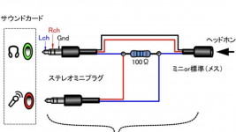
Would this setup work for the impedance?
Seems correct ( don't know how you're going to get signal onto the driver's terminals with that setup ? ), but what you really need to do is check all that against the REW Help File.
If you run into questions or need help with REW, ask those questions at the Official REW Help Forum .
🙂
I cross referenced that setup with the one in the rew manual, and seems the same. Will just connect speaker binding posts on the one side instead of that jack, and plug my speaker cables straight in.
Post 54 seems like it will be a good start. Again, my opinion is that this is the primary stuff (in this order):
1st, try setting the crossover higher
2nd, apply some eq to flatten the response
3rd, get a bigger & better horn
Point 1 is very basic. Crossing well under a horn's limit is bad (it is odd that this thread was active for 2 weeks and was read about 1,000 times before this got a mention). I'd suggest starting with steep, symmetric slopes, and worry about detail like asymmetric slopes later.
Point 2 start simple. Based on the FR plot in post 40:
2a) run the signal to the woofer amp at -8dB.
2b) take measurements at a few points (e.g. the listening spot and 1m either side of that). If any peak is present on all 3 measurements, that means it is probably "real" (that is: not just an artifact of the measuring position).
For such peaks, add a notch to reduce them, then re-measure to make sure it worked. Don't be too picky, and don't focus on getting it ruler-flat in one spot. Just try to get the average response a bit better than what you started with.
2c) Go back to 2a), and get the relative levels between the LF and HF drivers just right. Maybe -8dB isn't right, and -6dB or -10dB are better.
2d) add some HF boost, if needed.
2e) try moving the crossover point around. It will be easy to flip between 1200Hz to 1500Hz, and you might find that the horn sounds better when crossed higher.
Point 3 could be a whole other thread. My tip would be something Rubinesque (big with smooth curves), e.g. the biggest SEOS you can fit between the woofers.
Lots of the other points being raised are valid and well meant, but I think you can save them for later, and just do the basics first.
For example:
This is important to consider if you are using a cheap / bad woofer, less important in this case. The Beyma woofers are reported to be good, and measure well, with FR plots suggesting they suit a simple crossover. Money well spent.
I've attached a Beyma FR plot (extended and smooth) versus a driver with a pronounced breakup (big spike) to illustrate the difference.
Very useful for a passive crossover, but since you're using an active one, I think this is something you can skip for now.
1st, try setting the crossover higher
2nd, apply some eq to flatten the response
3rd, get a bigger & better horn
Point 1 is very basic. Crossing well under a horn's limit is bad (it is odd that this thread was active for 2 weeks and was read about 1,000 times before this got a mention). I'd suggest starting with steep, symmetric slopes, and worry about detail like asymmetric slopes later.
Point 2 start simple. Based on the FR plot in post 40:
2a) run the signal to the woofer amp at -8dB.
2b) take measurements at a few points (e.g. the listening spot and 1m either side of that). If any peak is present on all 3 measurements, that means it is probably "real" (that is: not just an artifact of the measuring position).
For such peaks, add a notch to reduce them, then re-measure to make sure it worked. Don't be too picky, and don't focus on getting it ruler-flat in one spot. Just try to get the average response a bit better than what you started with.
2c) Go back to 2a), and get the relative levels between the LF and HF drivers just right. Maybe -8dB isn't right, and -6dB or -10dB are better.
2d) add some HF boost, if needed.
2e) try moving the crossover point around. It will be easy to flip between 1200Hz to 1500Hz, and you might find that the horn sounds better when crossed higher.
Point 3 could be a whole other thread. My tip would be something Rubinesque (big with smooth curves), e.g. the biggest SEOS you can fit between the woofers.
Lots of the other points being raised are valid and well meant, but I think you can save them for later, and just do the basics first.
For example:
The cone breakup region is not ordinarily avoided with a horn system but needs to be negotiated
This is important to consider if you are using a cheap / bad woofer, less important in this case. The Beyma woofers are reported to be good, and measure well, with FR plots suggesting they suit a simple crossover. Money well spent.
I've attached a Beyma FR plot (extended and smooth) versus a driver with a pronounced breakup (big spike) to illustrate the difference.
build a measuring jig so that you can make impedance measurements.
Very useful for a passive crossover, but since you're using an active one, I think this is something you can skip for now.
Attachments


Yes, I expect I would start there.1200Hz, are they a fair starting point?
I wasn't concerned about any response peak.This is important to consider if you are using a cheap / bad woofer,
Thanks for all that. I have rigged up for measurements and will do as soon as wife leaves for work. A will do a couple, as suggested. I will do a few of the jbl only, and then 3 with the whole system is. Both drivers, with adjustment on attenuation. Will post in the next few hours. Will also post the measurement file will all the measurements on it. Hope that’s ok
Hi Brendan, I'd like posted following:
- impedance of tweeter (in enclosure)
- impedance of woofers wired in parallel (in enclosure)
- FR of tweeter, mic in the centre of the tweeter, 2 m away
- FR of both woofers wired in parallel, mic in the centre of the tweeter, 2 m away
- FR of upper woofer, mic in the centre of the tweeter, 2 m away
- FR of upper woofer and tweeter wired in parallel, mic in the centre of the tweeter, 2 m away
- FR of lower woofer, mic in the centre of the tweeter, 2 m away
- voltage setting the same for all measurements, perhaps 1Vrms
- exact locations of drivers in a baffle, distance from enclosure edges, horizontally and vertically
- gating (time window) for woofer measurement 20 ms, 5ms for the tweeter
- phase setting for FR measurements = minimum phase
Hi Lojzek
I am still having the jig for the impedance measurements made up, so can't supply that yet.
I have taken the following measurements and labelled them, as well as saved the file. They are namely:
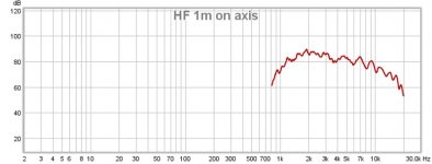
*FR of HF 1m away on axis
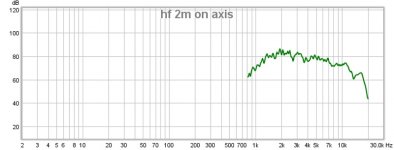
*FR of HF 2m away on axis
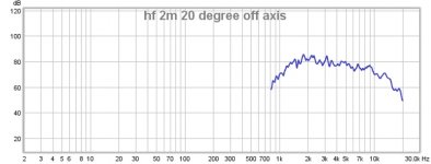
*FR of HF 2m away 20 degree off axis
*FR of HF at listening position
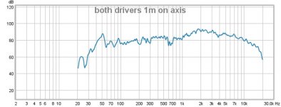
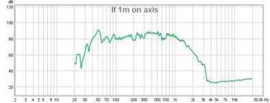
*FR of Woofer 1m on axis
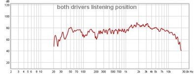
*FR all drivers at listening position.
This was done with the specs that I posted yesterday ie. new crossover points. Unfortunately, I could not match the levels exactly, but you will see in the graph. I am running separate amplifiers for HF and LF.
If you could elaborate on "gating"? I will try and sort out
*Also, what are you requiring for "minimum phase? I will attach the REW file, if you can save and open up with REW and check.
Baffle measurements to come through in the next few minutes.
I am still having the jig for the impedance measurements made up, so can't supply that yet.
I have taken the following measurements and labelled them, as well as saved the file. They are namely:
*FR of HF 1m away on axis
*FR of HF 2m away on axis
*FR of HF 2m away 20 degree off axis
*FR of HF at listening position
*FR of Woofer 1m on axis
*FR all drivers at listening position.
This was done with the specs that I posted yesterday ie. new crossover points. Unfortunately, I could not match the levels exactly, but you will see in the graph. I am running separate amplifiers for HF and LF.
If you could elaborate on "gating"? I will try and sort out
*Also, what are you requiring for "minimum phase? I will attach the REW file, if you can save and open up with REW and check.
Baffle measurements to come through in the next few minutes.
Attachments
Width of the baffle is 820mm
Height of the baffle 1220mm
Top driver is mounted 60mm down, with 220mm baffle space either side
Bottom driver is mounted 70mm up with 220mm baffle space either side
HF is mounted 42mm below the top and above the bottom drivers respectively, and has 300mm baffle space either side.
Measurements were taken from the edge of the driver frames, to the respective edges of the enclosure.
Hope this helps
Trying to zip the file to make the size compliant (The REW file)
Will post as soon as I have got it right.
Will post as soon as I have got it right.
😱Lojzek, the LF drivers are already wired in parralel to drop impedance to 4 ohm and mounted in cabinet. If I am to redo them, and do separate measurements, I would have to do this weekend.
Whatever suits you. Separate measurement of woofer+tweeter is for acoustical offset evaluation (delay) and the rest so I can simulate a passive filter.
The measurement of all drivers, is with the LF wired in parralel, and the HF, measurement taken from centre of the HF. Hope this helps. Thanks for your trouble Lojzek
Here are the REW "frd" files, now that I have worked it out
Attachments
- Status
- Not open for further replies.
- Home
- Loudspeakers
- Multi-Way
- New "Kinoshita" type build