Hi,
my experiments with 4 NJL diodes and 5 NJL diodes to temperature compensate the output stage bias current have proved unsuccessful.
I tried 4 diodes + resistor at 7mA and at 1.5mA, neither gave anything close to good temp comp. Always goes up with increasing temp.
I tried 5diodes + resistor @ 1.5mA. Bias Voltage far too high for a two stage EF.
Added a bypass resistor across one diode. Had to reduce this resistor so much that the 5th diode was passing <0.5mA (Vf~300mV).
Temp compensation was still poor but better than 4diodes.
I am now in the process of modifying the PCB/layout to incorporate a three stage EF with 5 NJL diodes and a series resistor.
Has anyone else managed to get good temp comp for the NJLs with either 4 or 5 NJL diodes? How did you do it? How well did it perform?
Hmm, Andrew,
Thanks for giving us your impressions.
Might be time to go to a BD139 Vbe multiplier with 1K5 from collector to base, and 330R with 200R trimpot in series from bass to emitter. Fit a quality 22uF bypass cap from collector to emitter.
Mounted atop one of the outputs, this works incredibly well on all my amps.
Always was a little sceptical about these diode installed outputs.
Cheers,
Hugh
By aksa - Might be time to go to a BD139 Vbe multiplier with 1K5 from collector to base, and 330R with 200R trimpot in series from bass to emitter. Fit a quality 22uF bypass cap from collector to emitter.
😀 This makes the "vaporware" NJL's quite useless , doesn't it ? The NJW's are the same die as the NJL's (minus the diode), but at 1.21 US $ , much more economical. The VBE on leads mounted atop an OP has survived the test of time and abuse for me. +- 1mv on the emitter resistors can be tolerated without unacceptable operaton
 or degradation of the sound quality in a standard type 2 EF.
BTW , I use 2.2k/680R (mje340) or (aksa's right on the money) 1.5k/450R with the BD's.
OS
Guys,
lets see how Carl's design shapes up before we make any determinations on these devices if only to validate Andrews findings.
lets see how Carl's design shapes up before we make any determinations on these devices if only to validate Andrews findings.
ULD Extreme
I agree with Doylep.
However, is it possible to perhaps cut a track and insert a vertically mounted schottky diode such as the 1N5819 for added tempco ?
SandyK
I agree with Doylep.
However, is it possible to perhaps cut a track and insert a vertically mounted schottky diode such as the 1N5819 for added tempco ?
SandyK
Fellas,
I would never call this my design. I may have contributed the PCB layout but the enhancements to the base design came from many of you! That way if the project turns out to be a success we can all share in the glow. And if the project is a bust I can point at all of you! 😀
I would never call this my design. I may have contributed the PCB layout but the enhancements to the base design came from many of you! That way if the project turns out to be a success we can all share in the glow. And if the project is a bust I can point at all of you! 😀
Carl,
I love it!!
IP is so over-valued anyway, I find..... most of the good amps just have a lot of work in the tweaking and refining, almost any topology can be made to sound really good with perseverance.
Hugh
I love it!!
IP is so over-valued anyway, I find..... most of the good amps just have a lot of work in the tweaking and refining, almost any topology can be made to sound really good with perseverance.
Hugh
the four NJL diodes can be used in a Leach type VBE multiplier.
If the Diode current is made adjustable (by bypassing some of the VAS bias) then the temp comp can be dialed in.
I found that 3off 1n4148 or 1n4004 had too low a temp co and 4off 1n4148 or 1n4004 had too high a temp co.
At the time I built the Leach's I did not know that the temp co could be altered by changing the diode current.
The PCB could have a couple of extra pads for the transistor, that could be linked across for ULD or Vbe for a Leach style.
How do you determine what the proper vbe is supposed to be and where is it measured. If there is not enough space here please lead me to a source.
Tad
Tad
the Vbe multiplier needs to supply a fixed voltage that matches the total of the Vbe drops of the output stage and the two Vre when the output is biased to it's operational current.
Assume for first guess that Vre = 20mV
Vbe of drivers and outputs = 600mV
total = 2.42V for a two stage EF
total 3.62V for a three stage EF (including the pre-drivers).
At low bias currents this total voltage is likely to be less, maybe even as low as 80% of that first guess.
5series NJL diodes will give ~2.0V to 2.5V. If the output stage requires <<2.42V you cannot insert a resistor to adjust the bias current.
Actually,
Adding a Leach style VBE multiplier to the design that used the embedded diodes would be pretty straight forward. Is that a worthy enhancement to the circuit and layout?
Or do we wait for Phoenix to tell us all how well the current implementation works? Thoughts? Concensus??
Adding a Leach style VBE multiplier to the design that used the embedded diodes would be pretty straight forward. Is that a worthy enhancement to the circuit and layout?
Or do we wait for Phoenix to tell us all how well the current implementation works? Thoughts? Concensus??
http://www.diyaudio.com/forums/showthread.php?s=&threadid=71534&perpage=25&highlight=&pagenumber=5
This page I've linked to even has the circuit diagram for the T-trak/leach scenerio.
OS
by douglas self - I think putting the T-Trak diodes in the Vbe multiplier as shown in your drawing is potentially an elegant way of running them at the lower current.
This page I've linked to even has the circuit diagram for the T-trak/leach scenerio.
OS
How are we looking gents?
Awfully keen to build one of these when the bugs are all ironed out 🙂
Awfully keen to build one of these when the bugs are all ironed out 🙂
Last Friday night I listened in some depth to the original SC design with Martin Logan ESS and Rega CD player front end. It was built by a fellow Melbourne Audio Club member, and uses my custom power supply, which has Nichicon Gold filter caps and four UFSR full wave rectifier blocks, one for each rail.
Not bad. Very quiet, good detail, but some transient instability at HF due to poor handling of the capacitive load of the MLs. But a better amp than most of the SC designs, I can vouch.
Paul (DoyleP), I look forward to seeing you when you have built the boards. I have several Aspen amps here you can compare it with, this is a useful comparison!
Hugh
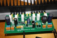
That looks really good Paul! Any problems with parts placement or layout issues? Be sure to let us know when you light that baby up.
Hugh,
What type/size of heatsinks did you use for the USFRs assuming TO220 ? I am using ug10dct ?
I am planning on completing a single block and playing with tempco, are you up for some tinkering when I complete it ? Possibly in the next week or so, thought I would complete this block yesterday but alas no VAS!
Peter.
That looks really good Paul! Any problems with parts placement or layout issues? Be sure to let us know when you light that baby up.
Thanks Carl, but its your design that made it easy... No real problems with the layout; from memory a couple of holes were under-sized. I have made a list of suggestions I will post when completed.
Peter.
Ah, Peter, my apologies Effendi,
I use a simple TO220 heatsink ONLY on the diode where both junctions are used. For those TO220 UFSR diodes where only one of the two internal diodes used, there is no heatsink required for 100% reliability. But don't go over about 10,000uF for 10A continuous rating diodes.
Cheers,
Hugh
I use a simple TO220 heatsink ONLY on the diode where both junctions are used. For those TO220 UFSR diodes where only one of the two internal diodes used, there is no heatsink required for 100% reliability. But don't go over about 10,000uF for 10A continuous rating diodes.
Cheers,
Hugh
- Status
- Not open for further replies.
- Home
- Amplifiers
- Solid State
- New Amplifier - ULD Extreme