One of the last things I added was the ability to regulate the power for the first stage. If you are powering the amplifier from a single supply you must add shorting wires to both rails. The pads that need to be jumped are marked on the silk screen. Did you do that?
One of the last things I added was the ability to regulate the power for the first stage. If you are powering the amplifier from a single supply you must add shorting wires to both rails. The pads that need to be jumped are marked on the silk screen. Did you do that?
Carl,
Yes the links were in place...
Hi,
my experiments with 4 NJL diodes and 5 NJL diodes to temperature compensate the output stage bias current have proved unsuccessful.
I tried 4 diodes + resistor at 7mA and at 1.5mA, neither gave anything close to good temp comp. Always goes up with increasing temp.
I tried 5diodes + resistor @ 1.5mA. Bias Voltage far too high for a two stage EF.
Added a bypass resistor across one diode. Had to reduce this resistor so much that the 5th diode was passing <0.5mA (Vf~300mV).
Temp compensation was still poor but better than 4diodes.
I am now in the process of modifying the PCB/layout to incorporate a three stage EF with 5 NJL diodes and a series resistor.
Has anyone else managed to get good temp comp for the NJLs with either 4 or 5 NJL diodes? How did you do it? How well did it perform?
I have been looking biasing and temp comp with TTraks in detail in simulation - see the thread I started: http://www.diyaudio.com/forums/showthread.php?t=151357
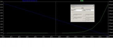
For this output stage, I found (in simulation) that you can get very good temp comp using 4 TTrak diodes with a resistor bypassing the whole string. You have to adjust the bypass resistor to get the right slope, this of course depends on the VAS current. Then adjust the resistor between the driver emitters to adjust the idle current. This assumes the drivers are mounted on the heatsink with the outputs so they track thermally.
With 7mA VAS current, bypass resistor = 470R and resistor between driver emitters = 360R is between 108 and 109mA between 20C and 100C. Beyond 120C though it starts to increase sharply so thermal protection should kick in at 100C - that would be prudent anyway.
Again, this is simulated results, your mileage may vary. Maybe somebody can try this out?
Attachments
your simulation seems very similar to what I said did not compensate.With 7mA VAS current, bypass resistor = 470R and resistor between driver emitters = 360R is between 108 and 109mA between 20C and 100C. Beyond 120C though it starts to increase sharply so thermal protection should kick in at 100C - that would be prudent anyway.
Again, this is simulated results, your mileage may vary. Maybe somebody can try this out?
your simulation seems very similar to what I said did not compensate.
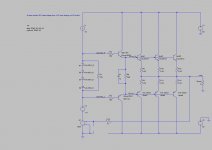
to be clear, here's the schematic used.
Attachments
readto be clear, here's the schematic used.
http://www.diyaudio.com/forums/showpost.php?p=1896550&postcount=321
Used a parallel resistor to adjust the diode current.
Used a series resistor to increase the bias voltage to turn on the output bias.
It fails to compensate for output temperature.
If your simulation appears to turn on the outputs with just 4diodes at a reduced current then your model is wrong.
Used actively above 150 Hz, is this amp stable into 2 ohms - the 2 ohms minimum at c 10 kHz?
Thanks
Thanks
I would have thought it was pretty obvious, because I have some excellent speakers of that min impedance, and am deciding which amp to use . .
read
http://www.diyaudio.com/forums/showpost.php?p=1896550&postcount=321
Used a parallel resistor to adjust the diode current.
Used a series resistor to increase the bias voltage to turn on the output bias.
It fails to compensate for output temperature.
If your simulation appears to turn on the outputs with just 4diodes at a reduced current then your model is wrong.
Andrew, I did read your post very carefully before my first post, however it wasn't exactly clear how you had the bias configured. If it is the same as the schematic I posted - well, that's why a picture is worth a 1000 words.
I agree that the simulation will only be as accurate as the models, I used the models direct from OnSemi for all components. If you, or someone else can measure the diode forward voltage and let me know the current and temperature I can compare that with the simulation. (I don't have any TTrak parts on hand.) AndyC has posted some modified models for the diodes, I can have a look at the behavior with those as well.
Attention all,
Hugh Dean has been busy working with Peter Doyle to debug his amplifier and they have found two layout mistakes! Both undoubtedly slipped in at the same time and are located in the same area of the PCB. The good news for those of you that have fabbed PCBs the fix is an easy one. By the time you have read this I will have updated the layout and gerbers that are online for download and post the URL again.
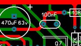
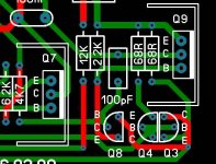
Error #1 before the fix
Hugh Dean has been busy working with Peter Doyle to debug his amplifier and they have found two layout mistakes! Both undoubtedly slipped in at the same time and are located in the same area of the PCB. The good news for those of you that have fabbed PCBs the fix is an easy one. By the time you have read this I will have updated the layout and gerbers that are online for download and post the URL again.
Error #1 before the fix
Attachments
Last edited:
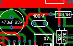
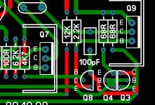
And now the fix to error #1. The trace between the 470uF cap and 10 ohm resistor is no longer shorted to the 100 pF cap
Attachments
Last edited:
And now the fix to error #2. The 100pF cap was not properly routed to the base of Q8
Attachments
Last edited:
Thanks to Carl, Hugh and Dean for their work. I imagine that these sent them a little stir crazy. Probably wanted to 🙁 😕 and 😡 and  and
and  but in the end their just 😎 and 😀.
Well done.
Terry 😱 (well I did check the board.)
and but in the end their just 😎 and 😀.Well done.
Terry 😱 (well I did check the board.)
Last edited:
Thanks Carl!!
No cigar yet. 🙁
Peter still has to come back in ten days for instalment two, where we fix the second mistake and actually trial the amp on the test bench.
These errors might require new boards as they are tricky to fix on the existing ones, but then, there are only three boards in existence, no big deal.
In the meantime Carl will work on the existing pcb and put up new gerbers for those who would like to build their own. 😉
Hang off until we get it going and playing music....... 😎
Cheers,
Hugh
I love this place. All of these highly skilled folks lending a hand for FREE.
When you start your project you know someone better than you has been there before. Good work. When you get it all tested I think I will try one of these. I think there are a few board houses still making small board orders for around 33.00.
Tad
When you start your project you know someone better than you has been there before. Good work. When you get it all tested I think I will try one of these. I think there are a few board houses still making small board orders for around 33.00.
Tad
Jeremy,
Another interesting fact is that the higher this resistor, the lower can be set the quiescent current. The math, based on crossover considerations, indicates that 26mV (derived from the Boltzmann constant) should be dropped across this resistor regardless, so 0.22R is passing 120mA and 0.1R SHOULD strictly be passing 260mA. It isn't in this design, so immediately there is one compromise....
Hugh
Based on this observation if raise the RE 0.22 to 100-ohm and connected in parallel to these capacitors 10000uF 10V?
Dynamic class A ?

- Status
- Not open for further replies.
- Home
- Amplifiers
- Solid State
- New Amplifier - ULD Extreme