I've finished my HP-2 and it sounds great on my old Grado SR60 'phones.
I had a small hiccup as I'd made a solder bridge between + & - on C3.
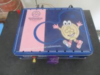
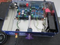
Attached are a couple of photos showing my continued use of biscuit tin chassis.
Now for some new headphones.
Many thanks Tom.
I had a small hiccup as I'd made a solder bridge between + & - on C3.
Attached are a couple of photos showing my continued use of biscuit tin chassis.
Now for some new headphones.
Many thanks Tom.
Attachments

Hi, finished my build and testing , a couple of questions if I may, voltage across TP1 and 2 are fine within range 13.48v & 13.8 v for a 28v power supply. For the reading across the output though I'm getting 44mv or so. I take it this is not good? How close to zero v should it be? Sorry newbe here.
Thanks
Thanks
Hi Not to worry . I put all the chips in and it's 2.9 MV and 3.0 mv on the outputs.
I also have sound 😀. Needed to put it on high gain for my HiFi man 400s.
Fun project to do and looks great in the chassis provided
Thanks!
I also have sound 😀. Needed to put it on high gain for my HiFi man 400s.
Fun project to do and looks great in the chassis provided
Thanks!

"Would there be any issues using HP-2 as a preamp as well?"
I have built 2 output XLR sockets into my chassis (not yet wired up) and I wanted to check their connections, please.
J2
Pin 1 Right output goes to Right XLR pin 2
Pin 3 Left output goes to Left XLR pin 2
Pin 2 Ground goes to L & R XLRs pin 3
Where does pin 1 of the XLRs connect to----just to the chassis?
Advice gratefully received.
stay safe
Last edited:
Pin 1 of the output jack should go to the chassis (which should connect to ground on the PCB through the RCA connectors).
Tom
Tom
Yesterday I purchased the boards.
I've almost got all the components sourced.
Cant wait to get started!
😀
I've almost got all the components sourced.
Cant wait to get started!
😀
Nice! I dropped your boards off at the post office yesterday. You should see them soon. Shipping seems to have mostly normalized, so expect a 2-3 week transit time.
Tom
Tom
Nice! I dropped your boards off at the post office yesterday. You should see them soon. Shipping seems to have mostly normalized, so expect a 2-3 week transit time.
Tom
Hey Tom,
Looking forward to work on this.
Thanks for your help and patience.
Almost there!
This has been a long time coming but I finally had some free evenings to put things together 🙂
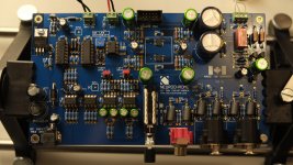
This is my second DIY project and seemed pretty daunting at first but I'm quite happy with how things went considering my soldering experience.
With the 28V input TP1 reads 14.7V, TP2 14.15V and output 0mV. I will hook up the headphone jack in the evening and finish the job 🙂
The one thing I'm kind of not happy with is the work on the two SOICs. I used the draw soldering method with some extra flux and it seemed to work well but I still had to reposition one of the chips a few times and it's still not exactly aligned perfectly with the pads nor is the solder super clean on some of the pads.
I suppose the question here is that should I resolder those two chips for a better finish? Will they possibly get damaged during resoldering and should I just scrap them and get new ones straight away?
Anyway, thanks to Tom for an interesting project so far! The instructions have been very good and thorough especially from the novice perspective.
This has been a long time coming but I finally had some free evenings to put things together 🙂
This is my second DIY project and seemed pretty daunting at first but I'm quite happy with how things went considering my soldering experience.
With the 28V input TP1 reads 14.7V, TP2 14.15V and output 0mV. I will hook up the headphone jack in the evening and finish the job 🙂
The one thing I'm kind of not happy with is the work on the two SOICs. I used the draw soldering method with some extra flux and it seemed to work well but I still had to reposition one of the chips a few times and it's still not exactly aligned perfectly with the pads nor is the solder super clean on some of the pads.
I suppose the question here is that should I resolder those two chips for a better finish? Will they possibly get damaged during resoldering and should I just scrap them and get new ones straight away?
Anyway, thanks to Tom for an interesting project so far! The instructions have been very good and thorough especially from the novice perspective.
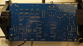
Attachments


I hooked up the headphone jack and tested sound. Right channel seems fine but on the left channel I'm getting a lot of static, a kind of screeching sound with the actual signal faint in the background.
I'm using the single ended Neutrik jack. When I touch the volume pot shaft to adjust the volume the static noise is a bit more faint. I have a TKD volume pot (2CP-601) which I had to mangle a bit to fit on the volume pcb but as far as I know this should fit ok in place of the Alps.
May I have damaged the SOIC chips while soldering if they were under heat too long?
I took another listen to the amp without the source attached. The noise is there as I turn on the amp but I also noticed that even when the amp is off there is still a very faint residual noise as long as the power cord is attached to the wall.
I also quickly tried a different ribbon cable for the volume pot but that didn't help with the noise.
I also quickly tried a different ribbon cable for the volume pot but that didn't help with the noise.
Well I don't know what happened but the noise seems to be gone and both channels now play fine. I removed the headphone jack for more measurements with the 400hz test tone and after reconnecting everything the sounds was fine.
Been playing music for few hours without hiccups.
Regarding measurements, the only sane and stable numbers I got from the TP1 and TP2.
From the output DC offset I get 0mV most of the time but something the values fluctuate a lot from 0mV to 15mV or so.
The AC readings from the outputs don't seem to care if there is sound playing or not and fluctuate from 0mV to 80mV pretty wildly.
Either I don't know how to measure correctly, my multimeter is not that great (Brymen BM257s) or getting a stable reading needs to have the probes inserted to the test points and absolutely not moving at all.
Is this kind of fluctuation normal or should I manage to get somewhat stable numbers from the outputs?
Anyway, I'll be doing some listening now 🙂
Noise can couple into the connection to the volume control. You'll likely find a big improvement once you get the circuit into a metal chassis. It sounds like you have solved it, though. It may be worthwhile to double check for bad solder joints and missing connections just to be sure. Your solder job looks really good, though.
Your soldering of the two SOICs looks pretty good. I wouldn't worry too much about one IC being rotated a little. I would clean up the flux on them, though.
Now you know why I sell a version of the PCB that has those ICs mounted... 🙂
Tom
Your soldering of the two SOICs looks pretty good. I wouldn't worry too much about one IC being rotated a little. I would clean up the flux on them, though.
Now you know why I sell a version of the PCB that has those ICs mounted... 🙂
Tom
Noise can couple into the connection to the volume control. You'll likely find a big improvement once you get the circuit into a metal chassis. It sounds like you have solved it, though.
Yeah seems like it. Although not knowing exactly what was causing the static initially does bother me a bit. Chassis will probably get rid of the last bit of noise I'm getting if I touch or turn the volume control. Otherwise the amp is noise free and sounds pretty awesome (I'm still burning it in + a fresh pair of Sennheiser 6XXs).
It may be worthwhile to double check for bad solder joints and missing connections just to be sure. Your solder job looks really good, though.
Thanks! I went through the joints but at least visually I couldn't find any clear suspects. I will go through the board one more time.
Your soldering of the two SOICs looks pretty good. I wouldn't worry too much about one IC being rotated a little. I would clean up the flux on them, though.
Now you know why I sell a version of the PCB that has those ICs mounted... 🙂
Tom
Great 🙂 Those two ICs were definitely the hardest part but I thought that in the worst case I'll probably just destroy the chips – that I can always get more of and try again so I took on the challenge. Soldering those was a good experience and next time will be easier.
I'm really grateful for this project so big thanks to Tom! I've learnt a lot while putting HP-2 together and listening to gear you built with your own hands is truly something else!
- Home
- Vendor's Bazaar
- Neurochrome HP-2 ultra-low distortion headphone amplifier