@Vunce,
Super nice job! I just got reminded from Nigel's post and ordered (4) of the Teko covers. 2 for this SMD version and 2 for JPS/2 pico's version with a cascoded JFET input stage. The ordering process from TME was super easy.
@nicoch58,
Thanks for the warning 😉.
Best,
Anand.
Super nice job! I just got reminded from Nigel's post and ordered (4) of the Teko covers. 2 for this SMD version and 2 for JPS/2 pico's version with a cascoded JFET input stage. The ordering process from TME was super easy.
@nicoch58,
Thanks for the warning 😉.
Best,
Anand.
Last edited:
Hi Vunce,
I like using the sockets for unobtainium jfets. I have a very small stash of 2SK170 and 2SJ74, and a matched pair used here can easily be used for another project if I want to in the future. (Also with sockets, so all is easily reversible.)
Plan for the PSU is to do something similar to the pics in this thread
CLC power supply for F3 in Apple computer case
This is the other project I have underway; the PSU is finished, the boards still underway. If I use another old Apple PC tower for the PSU for this M2 project then it will (a) match when standing side-by-side with the F3 one, or with the F5 monoblocks I did a few years ago in similar cases. These towers are convenient for separate PSU units since they are solid, quite nice looking and have plenty of ventilation and convenient carrying handles on top. Not to mention being free.
I'll probably do a CLC supply. I have an Antek AS-4218 transformer, some nice electrolytics I bought from a forum participant and some surplus chokes. These were sold to me (cheap) as 10A, 6.8mH and they look like they will do the job. Should give a nice standalone PSU to use with any future Pass or Pass-like design (ZM's LuDEF is in my sights...) in addition to using it for the present project. I expect I'll p2p a soft-start using Rod Elliott's circuit, like I did for the F3 supply. (Which weighs a TON, btw.) Layout inside the case may be different though.
Best
Nigel
Nigel,
I like that CLC supply in the Apple case! Especially seeing in situ the Hammond 195 series of chokes which gives me perspective as I am considering them in XRK's LUFO design.
Best,
Anand.
I like that CLC supply in the Apple case! Especially seeing in situ the Hammond 195 series of chokes which gives me perspective as I am considering them in XRK's LUFO design.
Best,
Anand.
Hi Anand,
A little OT. I thought the LuFo design looked fascinating. Since I have a few extra LU1014D (courtesy of jameshillj) I might give it a go. Although the heatsinking would be an issue. One way might be to use another Apple case; I have several of the coolers that I've taken out of these cases, so some diy arrangement with silent fans might be the way to get rid of all that heat. Of course this would mean putting the power supply elsewhere, but I can imagine two matching Apple towers, one with the power supply, one with the main circuit.
If you try the PSU idea in an Apple case, be aware that the exact geometry I used (with the big transformer in the old PSU case in the top to shield it a little) was VERY fiddly. I'm expecting to arrange this one for the M2 differently.
Best
Nigel
Hi Nigel,
If you haven’t seen this, check out these LU/LD1014D adapters XRK and JPS64 cooked up. Nice easy heatsink mounting of these little guys 😉
Lovoltech LU1014 Power Jfet Group Buy
If you haven’t seen this, check out these LU/LD1014D adapters XRK and JPS64 cooked up. Nice easy heatsink mounting of these little guys 😉
Lovoltech LU1014 Power Jfet Group Buy
Hi Vunce,
I saw those; they look good. For the F3 I've used an idea from older threads, and soldered them to short copper bars, with a screw on either side. Hopefully will work OK, although definitely not as pretty as those adapters.
Best
Nigel
I saw those; they look good. For the F3 I've used an idea from older threads, and soldered them to short copper bars, with a screw on either side. Hopefully will work OK, although definitely not as pretty as those adapters.
Best
Nigel
You may wish to consider making the same modification here, that member "palstanturhin" made to his F6. Like the M2, the F6 also has a K170/J74 JFET complementary follower input stage. He replaced it with a diamond buffer and felt the change improved the sonics on his F6.
Schematic in post #6077 and PCB layout in post #6075. Distortion measurements and frequency response in the neighborhood of post 6061.
Schematic in post #6077 and PCB layout in post #6075. Distortion measurements and frequency response in the neighborhood of post 6061.
Likewise, I have also replaced the JFet follower input stage in my F6 with a diamond buffer, modified from the Austin IPS to handle higher voltage. I like the way it sounds very much. It brings a similar quality to the F6 as it did to the M2x.
Hmmm....
Thanks for the info Mark, I wonder if the “Austin” daughter board could smoothly integrate as a front end to this M2 version. I’ll look into that 😉
Thanks for the info Mark, I wonder if the “Austin” daughter board could smoothly integrate as a front end to this M2 version. I’ll look into that 😉
Hi Anand,
Wow, lots of information in that link between you and TA! Thank you.
I haven’t built either amplifier yet, I started to gathering parts for the M2X, including the pcb’s, but then Prasi shared this version that includes SMD and the integrated TEKO shield. So, I do have the Austin pcb’s already.
This “Quicky” project looks to be getting a bit more “not so Quicky”
I did the same thing as Vunce; I have M2X boards sitting here doing nothing. On the other hand I hardly need more projects, even interesting ones like this.
Guys,
Get some music out of your amps first... then mod or build the next one! 😀
All the best!
p.s. None of us need more projects, but here we all are! 😀
Get some music out of your amps first... then mod or build the next one! 😀
All the best!
p.s. None of us need more projects, but here we all are! 😀
p.s. None of us need more projects, but here we all are! 😀
Amen Brotha!!

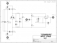
Have your high voltage engineers examine the Cedarburg (IPS8) card. There's a good chance they will conclude it can tolerate quite large supply voltage.
_
_
Attachments
Last edited:
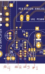
If one wanted to experiment “grafting” Mark Johnson’s Austin input stage pcb to this M2 layout, I believe this is how you’d go about it.
M2 PCB:__________ Austin Input stage:
J1 Drain = +V__________ Pin#3
J2 Drain = -V___________ Pin#1
J1/J2 Gate = Sig input_____ Pin#2
J2 Source pad = Output____ Pin#4
R4 Jumper
M2 PCB:__________ Austin Input stage:
J1 Drain = +V__________ Pin#3
J2 Drain = -V___________ Pin#1
J1/J2 Gate = Sig input_____ Pin#2
J2 Source pad = Output____ Pin#4
R4 Jumper
Attachments
Last edited:
- Home
- Amplifiers
- Pass Labs
- Nelson Pass M2