Vunce, back to my post #126
🙂
JFets are, logically, different issue - as you already concluded, solvable with sources trimpot
🙂
JFets are, logically, different issue - as you already concluded, solvable with sources trimpot
Thanks ZM.
Sometimes it takes a few hard hits to the head before the light goes on!
Extreme B, thanks for the tip. I’ll check what resistance is needed with the trimpot and replace with fixed resistors.
Sometimes it takes a few hard hits to the head before the light goes on!
Extreme B, thanks for the tip. I’ll check what resistance is needed with the trimpot and replace with fixed resistors.
use decent trimpot and do not bother with trimpotreplacingwithresistorsjungle OCD
if trimpots are good for that amp originator, in myriad of critical places, why bother?
if trimpots are good for that amp originator, in myriad of critical places, why bother?


Extreme B, thanks for the tip. I’ll check what resistance is needed with the trimpot and replace it with fixed resistors.
You should aim at matching the JFET's to get very close to 0V at the primary. This would be ideal.
I'll leave it to you to think/decide what you gonna do about the trimpot. A mix of ceramics and metal particles, in combination with contact resistance caused by a wiper scrabbing it, placed directly in a single path, surely is an undesired element.
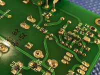
Tonight I continued fiddling with channel #2. I used a 20R Bourns 3296 style pot installed in sockets pre-adjusted to its midpoint, which in reality turned out to be 11R. (R3/R4 must be removed)
Powered up the M2 board and let the heatsink warm up to 48C°-50C°, 22mV DC was present at the Edcor input. Adjusted the trimpot until 0mV. Let the M2 cook a little while longer, no movement, stayed at 0mV. Then checked the output DC offset, 3-5mV - good there.
Shut down, removed M2 board from heatsink and pulled the trimpot, measured 15R3 and 8R. Found the closest resistors in my stash and soldered them in their respective R3/R4 positions.
Put everything back together and powered up, once heatsink was warmed up took more measurements.
0mV at Edcor input
1.3A bias current
3-5mV DC offset
She looks healthy enough to move on to Channel #1 for the same component replacements and Edcor input dc nulling mod.
Extreme B: my OCD won, Takman and Vishay MELF resistors are in the signal path 😉
Attachments
just a gentle reminder - input buffer DC offset fiddling is having nothing with amp output DC offset
🙂
🙂
Thanks for the guidance Fellas! I’m looking forward to getting the whole M2 package back together for some extended listening.
ZM, I threw in the output DC offset as a sign of good vitals 😉
ZM, I threw in the output DC offset as a sign of good vitals 😉
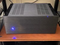
Another Pass Amp is Born!
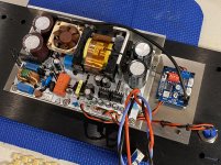
When the M2 boards were confirmed to work as they should with proper components, I moved on to fixing the background hum I was hearing approximately 12” away from the speaker. (Just a reminder, the power supply is a Micro-Audio SMPS500-CLA)
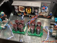
I tried all sorts of wiring schemes and even moved the SMPS outside the chassis, the hum didn’t change. Then I checked the psu output ripple with my Fluke, something I should have done first, and found 117mv. Next step was adding 22,000µF caps to each rail. That reduced the output ripple to 49mV, and the hum was noticeably reduced. Now I knew the path to follow. Next step, two cap boards were built with 4x 10,000µF caps and 0R22, 5w resistors on each rail at the cap board input per channel. Powered up…. Voila!! Silence at the speakers. The ripple was reduced from 117mV to 17mV, Happy Man!!
Then worked on mounting the SMPS on the front panel with a PWM fan control board w/thermocoupler to vary the speed of the Noctua fan depending on cooling demand. Thats about it, now time to listen and enjoy 😀
Just want to give a big thanks to Prasi for the nice tidy smd/th layout with integrated Edcor shield, Sami from MicroAudio, Zen Mod for steering me in the right direction understanding the M2 better, Extreme B for contributing to my OCD and Nelson Pass for sharing this design.

When the M2 boards were confirmed to work as they should with proper components, I moved on to fixing the background hum I was hearing approximately 12” away from the speaker. (Just a reminder, the power supply is a Micro-Audio SMPS500-CLA)
I tried all sorts of wiring schemes and even moved the SMPS outside the chassis, the hum didn’t change. Then I checked the psu output ripple with my Fluke, something I should have done first, and found 117mv. Next step was adding 22,000µF caps to each rail. That reduced the output ripple to 49mV, and the hum was noticeably reduced. Now I knew the path to follow. Next step, two cap boards were built with 4x 10,000µF caps and 0R22, 5w resistors on each rail at the cap board input per channel. Powered up…. Voila!! Silence at the speakers. The ripple was reduced from 117mV to 17mV, Happy Man!!
Then worked on mounting the SMPS on the front panel with a PWM fan control board w/thermocoupler to vary the speed of the Noctua fan depending on cooling demand. Thats about it, now time to listen and enjoy 😀
Just want to give a big thanks to Prasi for the nice tidy smd/th layout with integrated Edcor shield, Sami from MicroAudio, Zen Mod for steering me in the right direction understanding the M2 better, Extreme B for contributing to my OCD and Nelson Pass for sharing this design.
Attachments
-
 949BEF4B-F08D-45FA-B33D-DEC8293F7B18.jpg1 MB · Views: 272
 -
 D1F2D2CE-2990-4CFA-B305-B1123BBA945F.jpg733 KB · Views: 297
 -
 F1EE0983-3E03-4F64-8DE6-1C9250489B44.jpg1 MB · Views: 273
 -
 17FD7D2D-6C59-4720-AF9F-E5CBA9A8170E.jpg1,006.1 KB · Views: 281
 -
 3B806F8B-F998-45FB-B7BC-C62A596D622E.jpg877.9 KB · Views: 295
Last edited:


@Vunce
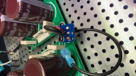
just one thing, splittin' da hair, all in name of good praxis - seeing how you did route mains wires though baseplate (wasn't easier just to pull them back to back plate, then push bellow base plate?)
when routing wire through hole in metal plate, proper is to route together natural pair of them - though one hole (say phase and neutral), and then also using some sort of grommet for hole
think eddy currents
I never pursued that issue in detail (how exactly effect is big in our builds), just avoiding one wire per hole is taking less efforts than involving the brain
Last edited:
Zm,
Well, in my haste to get the amp together for listening I forgot to flip the baseplate. In it’s current position the wires can’t go around and under the plate because the metal lip will pinch the wires between the aluminum cover and baseplate. I figured when I go back in for front end mods I’ll flip the plate then. You are correct about using grommets, to get by for now, the wires have double layered heat shrink wrap positioned where the wires enter/exit the perforated baseplate.
Thank you for the comps Fellas 🙂
- Home
- Amplifiers
- Pass Labs
- Nelson Pass M2