This sounds like a case of electrically conducted noise from the SMPS rather than magnetic. Looks like you did a good job shielding the Edcor transformers. The fact that the SMPS was putting out that much noise is somewhat disappointing.
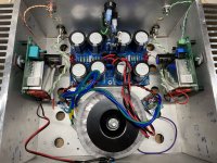
I just finished this one. Thanks to @wg45 for the spare boards. I bought paste and an air soldering station, and learned SMD soldering. I also got a little practice kit. It’s far easier than I imagined. Simple to set offset and. sound is great on bench speakers. Time to cook it and put in big speakers. I’ll play with H2 another day. The pot is set to dead center as measured.
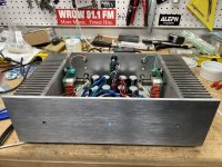
This old rawson chassis has Swiss cheese holes all over it. So far it has been F3, F3, and now M2.
I think I found an LED color that is close to the truckload of one’s that Nelson bought long ago. It’s Cyan. Close enough.
Thanks for a great set of boards and detailed BOM for the project!
This old rawson chassis has Swiss cheese holes all over it. So far it has been F3, F3, and now M2.
I think I found an LED color that is close to the truckload of one’s that Nelson bought long ago. It’s Cyan. Close enough.
Thanks for a great set of boards and detailed BOM for the project!
Attachments


I was going back through this thread and saw the notes on 1.2 vs 2.5V rating on D4 & D5. I'm using 2.5V in D4/5 (part 926-LM385BZ-2.5/NOPB) based on BOM at beginning of this thread. So I wondered if my bias would be wonky. I'm getting 1.3x Amps per rail on both channels. Should I order up and swap to 1.2V? Or leave as-is, since it seems to be working just fine...
This amp is really sounding nice on my medium speakers (JBL 4410 monitors). Nice 3D quality. Liquid spacious mids.
This amp is really sounding nice on my medium speakers (JBL 4410 monitors). Nice 3D quality. Liquid spacious mids.
2V5 diodes in M2 are having nothing with Iq - they're simply protecting optocoupler LED
even if 1V25 are in place, they're not conducting , so also having nothing with Iq
even if 1V25 are in place, they're not conducting , so also having nothing with Iq
NP talks about those LM385-1.2 diodes in his Official M2 Schematic thread. He is quite proud of them and indeed they are clever. NP says their job is to prevent the autobias negative feedback loop from slewing off into dangerous territory when the amplifier's output current exceeds 2x the DC bias current. Playing very loud into 4 ohm speakers, for example.
oh yes, clever indeed ....... he's my Pa, so what else to expect 
also worth noting, with years I learned that most interesting things are starting where Pa stopped with explanations
also worth noting, with years I learned that most interesting things are starting where Pa stopped with explanations
Amusingly, I revisited that circuitry recently and was surprised that I had been that clever.

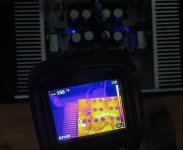
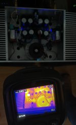
I had a home repair guy in the house today who was using a Flir thermal camera. When he was done I asked if he could look at “something I built recently”. Here’s the M2 with hot MOSFETs, source resistors, and mains CL60’s. I understand this is a $2000+ tool, so I don’t see myself buying one anytime soon. My laser thermometer gun is good enough. But since he was here and open to taking a pic, I thought it was a cool opportunity.
Attachments
Nelsons full explanation:
"
LM385's have important function that is not protection.
The 1.2V shunt reg is balanced off against the 1.2V forward bias of the
opto, and keeps the bias circuit from reacting to output current much greater
than the bias current.
This way you can go into Class AB mode with low impedance loads without
creating problems.
Without it, a high current transient would be interpreted as high bias, and
would drain the capacitor, requiring some time to recover.
 "
"
here: https://www.diyaudio.com/community/threads/official-m2-schematic.281520/page-118#post-5281512
"
LM385's have important function that is not protection.
The 1.2V shunt reg is balanced off against the 1.2V forward bias of the
opto, and keeps the bias circuit from reacting to output current much greater
than the bias current.
This way you can go into Class AB mode with low impedance loads without
creating problems.
Without it, a high current transient would be interpreted as high bias, and
would drain the capacitor, requiring some time to recover.
"here: https://www.diyaudio.com/community/threads/official-m2-schematic.281520/page-118#post-5281512
OK.......
fact is - Pa Mighty Mickey Brave Tailor, killed few of them with one stroke
he protected optoLed (fragile) and removed heavy peaks from bias integrator
first one is mandatory, second one is free lunch
fact is - Pa Mighty Mickey Brave Tailor, killed few of them with one stroke
he protected optoLed (fragile) and removed heavy peaks from bias integrator
first one is mandatory, second one is free lunch
[LM385-1.2] protected optoLed (fragile) and removed heavy peaks from bias integrator
first one is mandatory, second one is free lunch
I think R10 + R11 + R12 do a fine job of protecting the optoisolator's LED, all by themselves. Additional protection isn't needed and isn't mandatory.
Suppose the output current managed, somehow, to become 20 amperes (!!!) even though quiescent bias is only 1.3 amps. Then the voltage dropped across R13 + R14 will be (20 * (0.47 + 0.47)) = 18.8 volts, and the LED current is 41.8 milliamps*, thanks to R10+R11+R12. Vishay's datasheet for the optoisolator, attached below, says the maximum allowed forward current is 50mA and therefore: no damage. Additional protection besides R10+R11+R12 is not mandatory.
* (18.8 - 1.2) / (100 + 221 + 100) = 0.0418 amperes
_
Attachments
If nobody has, the simplest way is to send the Gerber files that Prasi nicely made available. Very simple via JLCPCB and you get to choose your favourite pcb colour (if that matters to you)
Eric
Eric
okay ...found it...If nobody has, the simplest way is to send the Gerber files that Prasi nicely made available. Very simple via JLCPCB and you get to choose your favourite pcb colour (if that matters to you)
Eric
thanks
- Home
- Amplifiers
- Pass Labs
- Nelson Pass M2