john curl said:Just turn the e to a J (American designation). For example J110, J112, J271 etc
Thank you very much.
BTW the J110 is still listed with status "Full Production" on the Fairchild website:
http://www.fairchildsemi.com/pf/J1/J110.html#Availability
Would it be still feasible to use them for the phono stage or are the more modern 2SK170 parts better. (The J110 datasheet gives no specification in terms of noise.)
Hi,
the lsk and 2sk are probably quieter than the Js.
You'll probably get away with B/Bl grade, but C/V grade may suit better.
What about 2sk369, does it improve on the J parts?
the lsk and 2sk are probably quieter than the Js.
You'll probably get away with B/Bl grade, but C/V grade may suit better.
What about 2sk369, does it improve on the J parts?
gk7 said:
Thank you very much.
BTW the J110 is still listed with status "Full Production" on the Fairchild website:
http://www.fairchildsemi.com/pf/J1/J110.html#Availability
Would it be still feasible to use them for the phono stage or are the more modern 2SK170 parts better. (The J110 datasheet gives no specification in terms of noise.)
J110 does not qualify as "low noise". In fact, I can't find any noise spec in the datasheet, which means that it's most likely pretty bad, and not guaranteed anyways.
Use 2SK170 or the much cheaper (and about the same performance) BF861 from NXP (former Philips Semiconductor). I just got a few hundreds from a reputable EBay seller, for $0.07 a pop. They are SMD, though.
Thank you for the info. The BF861 looks interesting, but being SMD it would be hard to match them. (I don´t know about any sockets for SMD where I could place them temporarily, so I think I stay with 2SK170).
The matched duals 2SK389 (and 2SJ109) would be nice too, but I have read about counterfeits sold, so I think it´s better to avoid them.
In short: Matched 2SK170 and 2SJ74 for the line stage and matched 2SK170 for the phono stage. Other options for the phono stage probably would be these duals:
2SK146 (Erno Borbely still has them, but they are expensive, EUR 20.50)
LSK389 (After some initial problems they are said to be quite good meanwhile: http://www.audioxpress.com/magsdirx/ax/addenda/media/colin2993.pdf )
gk7 said:The BF861 looks interesting, but being SMD it would be hard to match them. (I don´t know about any sockets for SMD where I could place them temporarily, so I think I stay with 2SK170).
Pressing with a needle against a SOT23 to DIP adapter landing pattern works very good for Idss measurements. Not as easy as TO92, but not really a big deal for the DIYer. Otherwise, SMD sockets are extremely expensive and are not much easier to handle.
You know there's a kit on e-bay?
http://global.ebay.com/STEREO_FET_LINE_AMPLIFIER_KIT_-_MARK_LEVINSON_JC-2/120307466306/item
http://global.ebay.com/STEREO_FET_LINE_AMPLIFIER_KIT_-_MARK_LEVINSON_JC-2/120307466306/item
Yes I know that this kit exists, but it is only very loosely
based on the original circuit and the replacement module I
intend to build will be designed to fit into my ML-1 (If
one of the modules should fail in the future.)
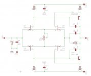
Now for part values and operating points:
I have heard that HKC is currently busy rebuilding the phono stage
and I hope he will share his experience here too.
For part numbers I refer to the attached schematic.
This is a preliminary draft, so comments, additions, suggestions etc.
are very welcome.
The FETs should be closely matched, I could get pairs matched
to within 0.5 mA of Idss, Is this close enough ?
Pavel Macura (who is a member here) has an interesting analysis of
distortion in JFET circuits on his website:
http://web.telecom.cz/macura/diyaudio/jfetdist.htm
Ideally all four FETs would be as equal as possible, so would it
be best to have matched quads ? (I wonder which quantity one would
need to check in this case).
I assume 10mA through each Fet for now, this results in 1V across
the drain resistors (R2,R3) and approx. 20mA trough each BJT. This is a
bit too low compared with the original. To increase this current should I:
a) Further increase the current through the FETs
b) Increase the drain resistors
c) Lower the emitter resistors
d) or use some combination of the above.
For example 120 Ohms for R2 and R3 should result in approx. 30mA
trough each output device (and 0.5W per device). The 2N2219A and
2N2905A (I just have some of them from earlier projects) are
TO-39 devices rated for 0.8W (I would put small heatsinks on them).
For higher currents we could probably use 2SA1209/2SC2911 with
heatsinks.
C1 and C2 are specified as 4.7 uF in the original. Given the
fact that modern parts are smaller I could substitute them with
small film types (6.8u polyester) or larger electrolytics (47 - 100u),
which would be better ? For the other caps I would use siver mica.
Resistors: Erno Borbely offers Caddock which are said to be excellent
but expensive. Or would (non-magentic) Dale be "good enough" ?
(Given the time I invest in this project and the value of the
ML-1 it is not my main concern to save money on the parts.)
based on the original circuit and the replacement module I
intend to build will be designed to fit into my ML-1 (If
one of the modules should fail in the future.)
Now for part values and operating points:
I have heard that HKC is currently busy rebuilding the phono stage
and I hope he will share his experience here too.
For part numbers I refer to the attached schematic.
This is a preliminary draft, so comments, additions, suggestions etc.
are very welcome.
The FETs should be closely matched, I could get pairs matched
to within 0.5 mA of Idss, Is this close enough ?
Pavel Macura (who is a member here) has an interesting analysis of
distortion in JFET circuits on his website:
http://web.telecom.cz/macura/diyaudio/jfetdist.htm
Ideally all four FETs would be as equal as possible, so would it
be best to have matched quads ? (I wonder which quantity one would
need to check in this case).
I assume 10mA through each Fet for now, this results in 1V across
the drain resistors (R2,R3) and approx. 20mA trough each BJT. This is a
bit too low compared with the original. To increase this current should I:
a) Further increase the current through the FETs
b) Increase the drain resistors
c) Lower the emitter resistors
d) or use some combination of the above.
For example 120 Ohms for R2 and R3 should result in approx. 30mA
trough each output device (and 0.5W per device). The 2N2219A and
2N2905A (I just have some of them from earlier projects) are
TO-39 devices rated for 0.8W (I would put small heatsinks on them).
For higher currents we could probably use 2SA1209/2SC2911 with
heatsinks.
C1 and C2 are specified as 4.7 uF in the original. Given the
fact that modern parts are smaller I could substitute them with
small film types (6.8u polyester) or larger electrolytics (47 - 100u),
which would be better ? For the other caps I would use siver mica.
Resistors: Erno Borbely offers Caddock which are said to be excellent
but expensive. Or would (non-magentic) Dale be "good enough" ?
(Given the time I invest in this project and the value of the
ML-1 it is not my main concern to save money on the parts.)
Attachments
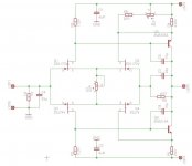
An additional question: On the bottom of the line modules two variable resistors can be seen. Maybe a later addition similar to the pot in the ML-2 frontend labeled "IM Balance". (See attachment and ignore the superfluous current source). No idea what IM stands for in this schematic. Intermodulation distortion ? To me it looks more like adjusting the offset by setting the same current in each output branch.
Attachments

A friend of mine he uses my boards to build his own JC-2. He has removed the two 22pF and two 10pF capacitors in the line stage. He said the high frequency has remarkable improvement.
What kind of caps did he use (before he removed) them ? The mica caps should have no influence on the audible high frequency range.
Assuming that we're talking about the same schematic, those caps limit bandwidth. Be careful about RF and circuit instability.
Grey
Grey
gk7 said:What kind of caps did he use (before he removed) them ? The mica caps should have no influence on the audible high frequency range.
He used mono caps. I am currently using 1% silver mica.
GRollins said:Assuming that we're talking about the same schematic, those caps limit bandwidth. Be careful about RF and circuit instability.
Grey
Yes, but he said the circuit is still stable without those caps and no RF interference has been detected.
HKC said:
Yes, but he said the circuit is still stable without those caps and no RF interference has been detected.
Well, as Grey has already said, this might invoke high frequency instability. Have you tested this into capacitive loads (like long cable runs) ?
You mention "mono caps", are these ceramic ? I would recommend mica or styroflex only.
hi,gk7 said:........ in the ML-2 frontend labeled "IM Balance". (See attachment and ignore the superfluous current source). No idea what IM stands for in this schematic. Intermodulation distortion ?
the current through the 806r feeds one FET and the tiny base current coming from the cascode.
The currents through the adjustment pot // 30r1 feed both the FET and the folded cascode.
The adjustment is there to balance the FET currents which can be measured as the difference between the source voltages.
I suspect this does change the distortion coming from the FET LTP.
Maybe it comes out as intermodulation.
Self talks about this adjustment as critical to LTP performance.
gk7 said:
Well, as Grey has already said, this might invoke high frequency instability. Have you tested this into capacitive loads (like long cable runs) ?
You mention "mono caps", are these ceramic ? I would recommend mica or styroflex only.
I think he did not test it into capacitive loads as what I seem he is running a cable with 1.5m long and he said it is fine.
The mono cap I meant is multilayer ceramic, according to Farnell data book, you are right. This kind of capacitors are much less money than silver mica but I still feel comfortable with using silver mica caps but thinking to use smaller value as long as the circuit is stable.
AndrewT said:hi,
the current through the 806r feeds one FET and the tiny base current coming from the cascode.
The currents through the adjustment pot // 30r1 feed both the FET and the folded cascode.
The adjustment is there to balance the FET currents which can be measured as the difference between the source voltages.
I suspect this does change the distortion coming from the FET LTP.
Maybe it comes out as intermodulation.
Self talks about this adjustment as critical to LTP performance.
Thank you for your comment, although your explanation seems more complicated than necessary. The pot (1k) and the resistor (10Ohms) simply is in parallel to the collector resistor (30.1Ohms) of the upper BJT. It allows for adjusting the current through this transistor. I think the purpose is to adjust the output stage for equal currents through both bipolars.
2nd try.
I have slightly increased the drain resistors and made the collector resistor of one BJT adjustable (12.5 - 32 Ohms) to adjust the output stage for equal currents through both BJTs.
Resistor brand: Vishay-Dale CMF-55-143 (good ? not good ?)
Currents: approx. 10mA for each FET (more ? less ?)
approx. 27mA for each BJT (they will dissipate 0.45W each, should be ok with small heatsinks).
Please comment, especially on the current through the FETs ...
Attachments
- Home
- Source & Line
- Analog Line Level
- Need to build JC 2 preamp