Transformers that overheat with no load in a sealed box would probably be expected to always overheat under the same conditions. What difference would you expect a DC power supply load to make in terms of overheating?
Probably the transformer you have needs more airflow, or you need to change to a more suitable type transformer for use in a sealed case, such as the one Terry Demol suggested. It shouldn't be too hard to figure out if airflow is an issue, why not try an obvious test?
Also, if it were to turn out that a DC power supply load made a helpful difference, it could just be because bleeder resistors always draw some current. Maybe that changes the nonlinear lossiness of the energy limited transformers a little bit for some reason?
Last edited:

Yes, you're probably correct, I doubt air flow is the issue. The control box has a cover and the entire unit has a cover as well (It's all off in the video). I don't think I could create enough airflow, inside our house where there is very little air circulation, to make a difference.
I think Terry was recommending the Toroidal transformer. I would like to give that a try, I just want to test this 250 VA unit a bit longer.
I don't know if switching to a DC power supply would be the fix, I was pointing out that the manufacturer did make some changes to the design, probably based partially on what I'm experiencing, and one of the change was a DC power supply .... I think, I'm still trying to find the schematic to the newer unit.
I recommended a Toroid as having the lowest no load current draw and as such likely lowest temp rise as that was the discussion point.Yes, you're probably correct, I doubt air flow is the issue. The control box has a cover and the entire unit has a cover as well (It's all off in the video). I don't think I could create enough airflow, inside our house where there is very little air circulation, to make a difference.
I think Terry was recommending the Toroidal transformer. I would like to give that a try, I just want to test this 250 VA unit a bit longer.
I don't know if switching to a DC power supply would be the fix, I was pointing out that the manufacturer did make some changes to the design, probably based partially on what I'm experiencing, and one of the change was a DC power supply .... I think, I'm still trying to find the schematic to the newer unit.
However moving on to safety and compliance issues this looks like a good option from a safety POV given the circuit breaker, steel end bells and quoted data sheet specs.
I guess it's up to you to decide your level of risk when it comes to who will do the install.
I went ahead and ordered one of the TR100VA001 Functional Devices transformers you recommended. If it's higher VA and better made, maybe it will perform better than the original. Plus, it will just barely fit in the control box so will be a better choice than the big 250 VA unit which will need to be mounted externally.
Thanks,
I'll report back.
Thanks,
I'll report back.
When you get it, connect directly to mains (unloaded) and see what happens in terms of temperature rise.
The connect a 24V lamp (or two 12V in series), low watts auto lamps, to the secondary, and let it reach stable temperature.
Then you will know if the circuit or the transformer were at fault.
That will help you find and clear the fault.
The connect a 24V lamp (or two 12V in series), low watts auto lamps, to the secondary, and let it reach stable temperature.
Then you will know if the circuit or the transformer were at fault.
That will help you find and clear the fault.
That's a good plan. I'll power it up with no load and run for a few hours to see if it gets hot like all the other transformers I have are doing.
And see the secondary is isolated, insulate the output wires with tape, or a dummy connector, open wires can cause accidents.
I was planning on welding them together with my Mig welder and then putting some electrical tape and a wire nut over .... but you idea makes more sense.
😉
It's been a long, miserable day, grant me this.
😉
It's been a long, miserable day, grant me this.
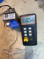
Results of the 96 VA TR100VA001 Functional Devices transformer with the primary powered and no load on the secondary: 106 degrees F or 40 degrees C.
A question for the transformer experts here. This is now the 4th transformer I've tested like this with no load on the secondary. All get hot, I'm assuming this is normal. (Although I did test the trans in a Threshold power supply and it did not get warm at all).
My thoughts, although I need more time to confirm with use:
-The original transformer was poorly designed / made and although was speced for continuous use, would trip it's built in thermal protection if left powered all the time.
-I think the 250 VA unit will work continuously and it's been in use for about 1 - 2 weeks now. It's hot but even Acme Transformer tech support claimed that was alright. It will be some work to incorporate this into the lift.
-This new 96 VA unit will just barely fit in the control / junction box. If I get past a month of use with the 250 VA trans (at which point I will be convinced it would work), I'm going to switch to the 96 VA TR100VA001 Functional Devices transformer unless anyone thinks that's a mistake. It would be an easy swap with just the addition of mounting holes.
If I do that, is the heat an issue? Shoud I put the cover back on the internal junction box or do you think the increase in heat inside that box could push that transformer to the point of tripping it's protection circuit? The more I think about it, someone earlier had mentioned that was why the cover was missing, it was a remedy for the overheating issue. I do remember the cover on that J-box getting very warm when I originally had this issue with the first transformer.
Thanks,
Eric
Attachments
1. What is the ambient temperature in the room, or the place you did the test?
2. Please see on light load, as it can be an inductor in off load condition.
3. The box should have holes, you can cut a hole and put mesh, or drill many small holes, enough to allow convective air flow (so top and bottom should have holes), 1/8" or so is good, large ones may let bugs in.
That should help a lot with your heat issue.
Good transformers get hot with no load when the primary voltage is higher than spec value or the mains waveform is distorted. Both conditions will cause saturation/losses on the iron. High quality transformers may have extra turns and more iron to cope with that, but standard control transformers are not built this way and their mitigation strategy is to tolerate high temperature. This explains why the Acme transformer tech support stated that it is fine to operate the transformer on your measured temperature. It would probabily still work just fine at 50+ celsius - so hot you will not be able to keep the finger on it. The timer next to it may not be so happy about the situation. Industrial environement often has this power supply issue. Before the widespread adoption of DC SMPS, it was common to see disproportionately big transformers to supply small loads inside a control unit. The transformer was already hot with no load, therefore the additional dissipation due to resistive losses in the copper had to be small, so the transformer had to be oversized.
Thanks. Sounds like I'm OK with either the 250 VA or 96 VA transformer and their heat. I know my voltage is good at 117 VAC, but do not have a scope to see if the waveform is distorted.
I had not given any consideration to the other components in the control box. If that is an issue then the externally mounted larger 250 VA trans. is the way to go.
At this point, I guess it's trial and error. I'll try the 96 VA TR100VA001 in the junction box, covered. If I have issues, I'll remove the J-box cover and try again. If still having temp. issues, then I'll switch to the externally mounted 250 VA unit.
Thanks,
Eric M.
An equivalent model of a transformer sometimes is shown like this:

Current flow it the primary winding that causes no load heating is mostly due loop indicated in red color. The part labeled nM is the mutual inductance which relates to the magnetic flux shared by both the primary and secondary windings. The other inductances (L1 and L2) may be referred to as leakage inductances, since they arise from flux that is not shared by both primary and secondary. Much of what causes heating under no load conditions is current flowing through nM which results in heating due to current flowing through the lumped equivalent resistance R1. Voltage across Rc also produces heating. Problem is that it costs money to make nM bigger, Rc bigger, and or R1 smaller, so less heating would occur under no-load conditions.
BTW, the letter n represents the turns ratio between the primary and secondary windings. Also, V1 is the primary winding voltage which in your case would be 120vac, and V2 is the secondary voltage which in your case would be 24vac. Rc represents a source of losses and heating related to iron core eddy currents and or hysteresis.
Don't know if that helps at all, but maybe it will?
Last edited:
You have maybe a dc component on the mains and you need a DC blocker.
https://sound-au.com/articles/xfmr-dc.htm
https://sound-au.com/articles/xfmr-dc.htm
The 96 VA TR100VA001 Functional Devices transformer shouldn't be getting hot unloaded, I covered that. It's specced to run (presumably well below saturation) for 50 Hz operation so at 60Hz there will be some 'core headroom'Good transformers get hot with no load when the primary voltage is higher than spec value or the mains waveform is distorted. Both conditions will cause saturation/losses on the iron. High quality transformers may have extra turns and more iron to cope with that, but standard control transformers are not built this way and their mitigation strategy is to tolerate high temperature. This explains why the Acme transformer tech support stated that it is fine to operate the transformer on your measured temperature. It would probabily still work just fine at 50+ celsius - so hot you will not be able to keep the finger on it. The timer next to it may not be so happy about the situation. Industrial environement often has this power supply issue. Before the widespread adoption of DC SMPS, it was common to see disproportionately big transformers to supply small loads inside a control unit. The transformer was already hot with no load, therefore the additional dissipation due to resistive losses in the copper had to be small, so the transformer had to be oversized.
as core magnetization level is inversely proportional to frequency, IOW 1/2 freq = 2 x core mag level.
I did not realize Eric did not have a Cro, also hasn't checked for DC on mains.
It does indeed point very much toward DC on mains.
All above being said, the FD Transformer is worth using considering the circuit breaker.
- Home
- General Interest
- Everything Else
- Need Some Advice Regarding a Handicap Lift, Odd Transformer Issue