Signal ground and power ground are sometimes loosely coupled through resistors and capacitors. Should be possible to glean from the schematic.Reading 0 ohms on most places on chassis screws except for one place were inputs connect to input board. Is this normal? Here I’m reading 56ohm

Irrespective of the health status of IC501, IC502, the behavior at pins 8 and 4 should be about the same due to bypassing provided by C525 (and C518, C519).
If I interpret correctly, pin 8 shows "ugly" behavior but the waveform looks better at pin 4. I suggest using the ugly signal as a "test waveform" and follow it from pin 8 along the path to pin 4, perhaps using a "divide and conquer" search. eg. is the top of C525 ugly, or better? How about bottom of C525? Try to probe directly on component leads, as this can help localize unrecognized broken traces.
If I interpret correctly, pin 8 shows "ugly" behavior but the waveform looks better at pin 4. I suggest using the ugly signal as a "test waveform" and follow it from pin 8 along the path to pin 4, perhaps using a "divide and conquer" search. eg. is the top of C525 ugly, or better? How about bottom of C525? Try to probe directly on component leads, as this can help localize unrecognized broken traces.
Both supplies are from the same winding, but the pre has it's own 4 diodes, and caps.Should I interpret this as the 81V rail being unstable (and possibly tripping the relay) when you touch the probe to it?
It looks like you have two separate power supplies. Did you test both of them? One seems to be connected to CN6 and appears to power the preamp. Are your getting stable voltage from it when it’s disconnected from the amplifier board?
It's a sturdy supply, with the diodes fed though 5A fuses.
The weak link is the plugs and relay contacts.
The scope would need to be set with about 20us divisions to look at ripple. I can't see a thing with the entire history of man on the screen.
The latest volt readings show +3.2v and -2v at the zeners. Then further along the same wire this 11-12v. This hints at a changing state during testing. As does past talk of different behaviour each power up.
Relay 501 needs a good looking at. As does the DC on a timebase that would show ripple.
I keep sticking my head in, as I don't want to miss the ending. It's great to see some new faces to. It might not be long now.
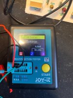
I pulled the L501 inductor now that I got a new component tester and it’s reading 30uH instead of 18uH not 100% sure my TC from JoyIt is correct here but it is reading good on everything else I have tried so far. If this is out of spec maby this could be a reason, it’s just in the area we’re in having problem. Any thoughts here?
Removed both Op-amps and now I got no problems probing around. I will se if I can find the old op amps
Try feeding, say, 1kHz 100mV p/p on the input and see what you get out at the coil. Maybe the preamp is working. That would be one less thing to worry about.
I don't have a decent signal generator yet. But i feeded the amp a 1K signalt from my phone, and not really able to hook the terminal 100% with scope probe but i'm ablte to get a signal true. What i cant understnad is that when i try to put the volume knob up the waveform flatens out.
What do you mean by “flattens out”? The tops get clipped off?
But at least you have signal coming through. What’s the amplitude of your input (you can check that with your scope)
But at least you have signal coming through. What’s the amplitude of your input (you can check that with your scope)
View attachment 1417962
Mate, I mangage to set the input from phone to about 100mV (i think) and powering amp on and givin it maby 10-15% volume. Please help me if i'm still doing it wrong.
Mate, I mangage to set the input from phone to about 100mV (i think) and powering amp on and givin it maby 10-15% volume. Please help me if i'm still doing it wrong.
Not sure what you mean. I have signal set at about 100mV a freq of 1K. Where do you want me to put by scope at? This output from speaker temrinal with an input of about 100mV.

How are you expecting to have any output on the speaker terminal when you pulled the opamps? Well, you have something, but it’s probably something that leaks through some path somehow. I don’t have the time to check the schematic.
Probe right after the preamp at the coil you measure the other day.
Please familiarize yourself with the topology of this amplifier!
Probe right after the preamp at the coil you measure the other day.
Please familiarize yourself with the topology of this amplifier!
I'm feeling stupid now. The signal from RCA input feeds into a Input board as follows bellow:

It then feeds to amplifier board via CN12. The signal volume is controlled VR501. The signal then goes via grey(black) to speaker board. I do measure on these connections on speaker board. There is now preamplifer per definition, or im totaly wrong here. I can measure the signal just before it goes true amplifer on R501.

It then feeds to amplifier board via CN12. The signal volume is controlled VR501. The signal then goes via grey(black) to speaker board. I do measure on these connections on speaker board. There is now preamplifer per definition, or im totaly wrong here. I can measure the signal just before it goes true amplifer on R501.
- Home
- Amplifiers
- Solid State
- Need help with oscillating amplifier (Denon POA)