OK great i will get that book!My 2 cents from Finland. Try to find this book somewhere, you will find it's very helpful and practical. My copy have a message from Bob Pease and it seems you don't have "middle-sized trouble", sorry can't help any more.
View attachment 1417491View attachment 1417492
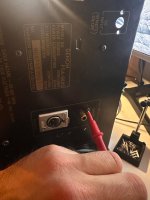
Okey this is probobly not okay and you guys will have a laugh... here is a video of when i try to measure what happens when amp goes "wild". This happens when i instert a probe in certain areas. +
Should I interpret this as the 81V rail being unstable (and possibly tripping the relay) when you touch the probe to it?
It looks like you have two separate power supplies. Did you test both of them? One seems to be connected to CN6 and appears to power the preamp. Are your getting stable voltage from it when it’s disconnected from the amplifier board?
It looks like you have two separate power supplies. Did you test both of them? One seems to be connected to CN6 and appears to power the preamp. Are your getting stable voltage from it when it’s disconnected from the amplifier board?

It would help to know what we’re looking at. The output?Okey this is probobly not okay and you guys will have a laugh... here is a video of when i try to measure what happens when amp goes "wild". This happens when i instert a probe in certain areas. +
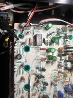
View attachment 1417495
It’s definitely oscillating when you put the probes on it.
I believe you can break the preamp and power amp apart at the coil right after the node where the zeners meet. That way you can test them in isolation. Maybe you can try to disconnect the stages from each other and see what you get out from the preamp and if that’s where the oscillations are coming from.
Yes the supply to the right for the output transistors and that part of there board is stable. No problem probing there. Not the same on the other side probing the positive 81 is no good but negative seems better though.Should I interpret this as the 81V rail being unstable (and possibly tripping the relay) when you touch the probe to it?
It looks like you have two separate power supplies. Did you test both of them? One seems to be connected to CN6 and appears to power the preamp. Are your getting stable voltage from it when it’s disconnected from the amplifier board?
Whis looking at pin 8 on IC501It would help to know what we’re looking at. The output?
It’s definitely oscillating when you put the probes on it.
I believe you can break the preamp and power amp apart at the coil right after the node where the zeners meet. That way you can test them in isolation. Maybe you can try to disconnect the stages from each other and see what you get out from the preamp and if that’s where the oscillations are coming from.
Could I have ground problems? Also inserting rca to line in and touching chassi some areas make the amp oscillate.
If I understand correctly, behavior at pins 8 versus 4 is different? This makes me suspicious of C525, as the two pins should behave similarly. Check integrity of the cap and traces.
Remove the opamps and test them on a breadboard. They’re probably fried from having seen 71V on their supplies. Also make sure that the supply voltages for all the opamps are within the recommended range.
As someone pointed out, the opamps you put in are faster and have higher gain than the originals. For giggles, try to put in a TL072 or TL082 (but after you’ve checked the voltages).
Maybe try a larger Miller capacitance on IC501.
Try pulling the opamps out and cut the supply to the power amplifier and see if you can get the preamp to behave nicely when the opamps and power state are out of the equation.
If you haven’t already done so, isolate the the preamp power supply and make sure it behaves nicely.
But most of all, make a plan instead of randomly probing! Do you understand what the different parts of the schematics do and where the feedback loops are?
I was just going to suggest that. With amplifier turned off and the capacitors discharged, what resistance do you measure between the ground nodes on the board and PSU ground?Could I have ground problems? Also inserting rca to line in and touching chassi some areas make the amp oscillate.
Yes is seems so I will recheck that and also pull 525 and test it. I did at one point install new one kemet film cap there but to be safe I’ll check all caps in that area .If I understand correctly, behavior at pins 8 versus 4 is different? This makes me suspicious of C525, as the two pins should behave similarly. Check integrity of the cap and traces.
Please also check that opamp before you do anything else! You probably fried it when that zener was faulty. Any of the three opamps are bad, your results will be completely unreliable.
C518 and C519 also parallel C525, so they deserve scrutiny also. Main point is that bypassing across pins 4 and 8 should ensure similar behavior. Is there about 30VDC between the 8 and 4 pins?
I just installed 2 new op amps yesterday so they should be fresh.Remove the opamps and test them on a breadboard. They’re probably fried from having seen 71V on their supplies. Also make sure that the supply voltages for all the opamps are within the recommended range.
As someone pointed out, the opamps you put in are faster and have higher gain than the originals. For giggles, try to put in a TL072 or TL082 (but after you’ve checked the voltages).
Maybe try a larger Miller capacitance on IC501.
Try pulling the opamps out and cut the supply to the power amplifier and see if you can get the preamp to behave nicely when the opamps and power state are out of the equation.
If you haven’t already done so, isolate the the preamp power supply and make sure it behaves nicely.
But most of all, make a plan instead of randomly probing! Do you understand what the different parts of the schematics do and where the feedback loops are?
All this is a great input and I will try this tomorrow, now my dog needs some attention.
I will try a 1uf TDK ceramic. Should I try them in parallel do you think?
After reading this thread more, IC501 is originally NJM082BD, correct ? Like this one :
https://www.digikey.com/en/products/detail/nisshinbo-micro-devices-inc/NJM082BD/11685385
The other one IC502 is some dual one, but which one ? And both are changed to "something better" new ones. Why not try original ones when they seems to be available and check also that all zeners and voltages are ok before destroying new parts ? These modern faster op-amps can oscillate in this circuit, but not sure about this. Here is many members who knows this better than me.
Will check.C518 and C519 also parallel C525, so they deserve scrutiny also. Main point is that bypassing across pins 4 and 8 should ensure similar behavior. Is there about 30VDC between the 8 and 4 pins?
The 1uf 100v are replaced with:
https://www.mouser.se/ProductDetail/KEMET/R82EC4100Z370K?qs=MdJgNetHbfnzRxbVzlx9GA==
And all the other ones in the area are ceramic 0GC types. The 220uf are nichicon audio grade don’t remember serie.
Thanks mate. I’m thinking of removing both op-amps to se what happens and also trying installing old op-amp it think they are om good.After reading this thread more, IC501 is originally NJM082BD, correct ? Like this one :
https://www.digikey.com/en/products/detail/nisshinbo-micro-devices-inc/NJM082BD/11685385
The other one IC502 is some dual one, but which one ? And both are changed to "something better" new ones. Why not try original ones when they seems to be available and check also that all zeners and voltages are ok before destroying new parts ? These modern faster op-amps can oscillate in this circuit, but not sure about this. Here is many members who knows this better than me.
IC501 | NJM082DT | to OPA1642AIDR | |
IC502 | M5218P | to OPA1656ID |
Reading 0 ohms on most places on chassis screws except for one place were inputs connect to input board. Is this normal? Here I’m reading 56ohmI was just going to suggest that. With amplifier turned off and the capacitors discharged, what resistance do you measure between the ground nodes on the board and PSU ground?
Attachments
- Home
- Amplifiers
- Solid State
- Need help with oscillating amplifier (Denon POA)