Hello all!
I would really appreciate any help i could get here since i've been working on this amplfie for way to long and i'm still having problems. I have invested in a new scope to se if i can get any leads. Since i'm new to using scopes and in general an amature i have realy no idea what to make of these measuements down below.
The problem i'm having is that the amplfier seems to oscillate and cause my voltage rails to drop and my DBT is flashing slowly and low. Powering on amp with CN6 connected i'm able to get out of protection for about 5 seconds and then relay kicks in and protection light goes back on. Most parts on amplifer board are replaced with new ones and all elektrolytic capasitors are replace with new quality ones. The measurments down below are with and without CN6 connected. The scope is set to AC Couple because something is telling me im getting AC-ripple or oscillation from AC?
Main amp board:

PSU

Pic 1 probes at red and black from PSU (pink position) : CN6 disconnected . FFT 10Khz (I'm having problems setting trigger point becuase waveform is jumping all over the place, up and down)
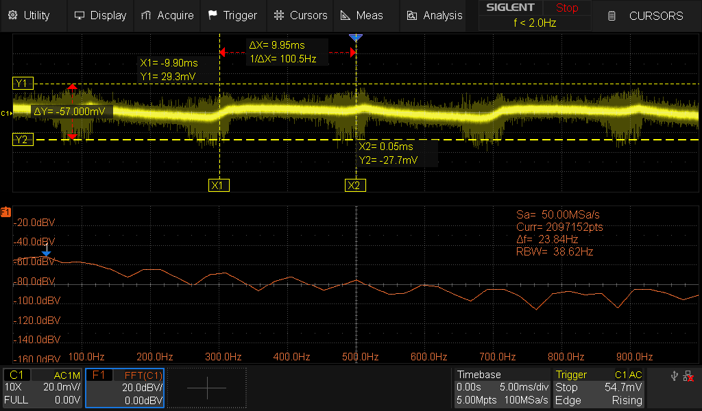
Pic 2: Same as above but FFT 25Mhz (high freq)

Pic 3 probes at red and black from PSU (pink position) : CN6 connected. FFT 10Khz (waveform more steady!)

Pic 4: Same as above but FFT 25Mhz (high freq) (waveform more steady!)

Pic 5: probes at CN13 position from CN6 disconnected . FFT 10Khz

Pic 6: probes at CN13 position from CN6 disconnected . FFT 25Mhz (high freq)

Pic 7: probes at CN13 position from CN6 connected. FFT 10Khz

Pic 8: probes at CN13 position from CN6 connected. FFT 10Khz
Pic 9: probes at CN13 position from CN6 connected. FFT 25Mhz (high freq) (2.2V ac coming true?)

Pic 9: Probes at test point 1 & 2: CN6 Connected. FFT 10Khz

Pic 9: Probes at test point 1 & 2: FFT 25Mhz (high freq)

What can be the cause of this. Maby Brdige rectifier are failing at load or anythin else to concider?
I would really appreciate any help i could get here since i've been working on this amplfie for way to long and i'm still having problems. I have invested in a new scope to se if i can get any leads. Since i'm new to using scopes and in general an amature i have realy no idea what to make of these measuements down below.
The problem i'm having is that the amplfier seems to oscillate and cause my voltage rails to drop and my DBT is flashing slowly and low. Powering on amp with CN6 connected i'm able to get out of protection for about 5 seconds and then relay kicks in and protection light goes back on. Most parts on amplifer board are replaced with new ones and all elektrolytic capasitors are replace with new quality ones. The measurments down below are with and without CN6 connected. The scope is set to AC Couple because something is telling me im getting AC-ripple or oscillation from AC?
Main amp board:
PSU
Pic 1 probes at red and black from PSU (pink position) : CN6 disconnected . FFT 10Khz (I'm having problems setting trigger point becuase waveform is jumping all over the place, up and down)
Pic 2: Same as above but FFT 25Mhz (high freq)
Pic 3 probes at red and black from PSU (pink position) : CN6 connected. FFT 10Khz (waveform more steady!)
Pic 4: Same as above but FFT 25Mhz (high freq) (waveform more steady!)
Pic 5: probes at CN13 position from CN6 disconnected . FFT 10Khz
Pic 6: probes at CN13 position from CN6 disconnected . FFT 25Mhz (high freq)
Pic 7: probes at CN13 position from CN6 connected. FFT 10Khz
Pic 8: probes at CN13 position from CN6 connected. FFT 10Khz
Pic 9: probes at CN13 position from CN6 connected. FFT 25Mhz (high freq) (2.2V ac coming true?)
Pic 9: Probes at test point 1 & 2: CN6 Connected. FFT 10Khz
Pic 9: Probes at test point 1 & 2: FFT 25Mhz (high freq)
What can be the cause of this. Maby Brdige rectifier are failing at load or anythin else to concider?
Attachments


Last edited:
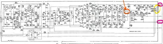
At a first glance, that looks like stray switch mode noise to me, but I'm having trouble understanding exactly how you're probing. What's your ground reference? The test point you've got circled seems to be for setting the bias. Not sure that's the best place to probe. What does the output look like? Does it oscillate?

Did the amplifier work before the extensive service was done?
The bias test point is a summation of both channels, so doesn't narrow things down much. For that, I would look at either of the two points, compared to earth, not the other point/channel.
The bias test point is for dc measurements, and you might expect 10mV there, maybe 20, it's in the low figures. If it's higher then perhaps that is pulling the psu rails down. Which is quite a lot of power I imagine. If it's both rails, bias might be the issue. If one rail, perhaps an output is down.
So, as the only service adjustment on the board, and one capable of being at fault, what is the bias
Is it? It looks like the difference between positive and negative leg on the output stage to me. There's only one channel in that schematic.The bias test point is a summation of both channels
Another thing: Those oscillations look like they're about 400mV p/p. Even if they're real (and not just switch mode garbage making it's way in through probing errors), it shouldn't be enough to trip the overcurrent/speaker protection.
You don't happen to have DC on the output, do you?
You don't happen to have DC on the output, do you?
No it was blowing fuses and previous owner had some work done but gave up.Did the amplifier work before the extensive service was done?
Thanks. I’m god probe at black 0v and red +81v wires coming from PSU to amp board, they are just after 4filter capes rated 10.000uf 100V. After some probing around my rails will drop to about +-74v when CN6 connected removing it will get my 81v back. Ok never mind test points.At a first glance, that looks like stray switch mode noise to me, but I'm having trouble understanding exactly how you're probing. What's your ground reference? The test point you've got circled seems to be for setting the bias. Not sure that's the best place to probe. What does the output look like? Does it oscillate?
I’m also probing at CN13 which is connected to PSU which also provide +-81v to main amplifier.
What is switch mode noise? And what might be a way to approach it? Thanks !
Thanks mate. The bias is set to zero I have my trimmed set fully anti clockwise. At some point I was a let to have stable voltages until I start to probe around OR trying to set bias, just getting some mV I amplifier started to oscillate and pulling voltages down and DBT lights up.The bias test point is a summation of both channels, so doesn't narrow things down much. For that, I would look at either of the two points, compared to earth, not the other point/channel.
The bias test point is for dc measurements, and you might expect 10mV there, maybe 20, it's in the low figures. If it's higher then perhaps that is pulling the psu rails down. Which is quite a lot of power I imagine. If it's both rails, bias might be the issue. If one rail, perhaps an output is down.
So, as the only service adjustment on the board, and one capable of being at fault, what is the bias
I will check, just to be sure do you mean on my me speaker terminals? 🙂Another thing: Those oscillations look like they're about 400mV p/p. Even if they're real (and not just switch mode garbage making it's way in through probing errors), it shouldn't be enough to trip the overcurrent/speaker protection.
You don't happen to have DC on the output, do you?
What does this mean?The bias test point is a summation of both channels, so doesn't narrow things down much. For that, I would look at either of the two points, compared to earth, not the other point/channel.
The bias test point is for dc measurements, and you might expect 10mV there, maybe 20, it's in the low figures. If it's higher then perhaps that is pulling the psu rails down. Which is quite a lot of power I imagine. If it's both rails, bias might be the issue. If one rail, perhaps an output is down.
So, as the only service adjustment on the board, and one capable of being at fault, what is the bias
“Oh yeah.. P ch N ch, banks.”👍✌️
Switch mode noise comes from switch mode power supplies that are present in pretty much any electronics these days. It's radio frequency, so it can travel through wires as well as through air. You don't want it in your amplifier for signal quality reasons, but it's not going to cause any catastrophic issues like the ones you're describing.
What does CN6 go to? The speakers? If you don't have any signal on the amplifier, connecting the speakers should NOT make the power supply drop voltage like that. You have two possible problems:
1. You have DC voltage on your output. Stick a voltmeter in DC mode between the speaker output (gray) and ground, or measure with your scope in DC coupled mode. You should only see a very low DC voltage, preferably in the 10mV range or lower. Zero is what you're going for. If you have >100mV you could get sound quality issues. If it's several volts, you risk burning your speakers. DC on the output is BAD! Very BAD! Check that first.
2. You have heavy oscillation. Stick a scope probe on the output. You preferably want a flat line. Oscillations are always bad and something you need to address. However, if the amplitude is fairly low, it's not going to trip the protection circuit.
I'm having my suspicion that you may have DC on the output. Let's check!
Pic on main amp board. There are two jfets at Tr500 and 501. They are replaced with new ones but on adapter board. https://www.mouser.se/ProductDetail/Toshiba/2SK209-GRTE85LF?qs=8TQFHmocP6xDVEMkPbnGBw==

No no no no!!! You should never EVER probe like that unless you have a differential probe! Luckily for you, modern scopes don't have the scope ground connected to earth ground. With an older scope, there would have been smoke! Never EVER connect the ground lead to anything other than ground! (Yes, you technically can with a modern scope, but you're not going to get a good measurement and you may still blow things up if the other probes are grounded)
Either way, probing those two test points isn't going to tell you anything interesting. You need to start by taking two very simple measurements: DC voltage between output (gray) and ground (it should be >10mV preferably and definitely >1V or you have big problems). Next put the scope probe between output (gray) and ground. You should not see any oscillations. Post the results!
Either way, probing those two test points isn't going to tell you anything interesting. You need to start by taking two very simple measurements: DC voltage between output (gray) and ground (it should be >10mV preferably and definitely >1V or you have big problems). Next put the scope probe between output (gray) and ground. You should not see any oscillations. Post the results!
Thanks for helping me. When powering up and when relay clicks my multimeter set on red and black speaker terminal it goes to OL then the voltages is jumping up and down between 0-50mV. Not settling down.Switch mode noise comes from switch mode power supplies that are present in pretty much any electronics these days. It's radio frequency, so it can travel through wires as well as through air. You don't want it in your amplifier for signal quality reasons, but it's not going to cause any catastrophic issues like the ones you're describing.
What does CN6 go to? The speakers? If you don't have any signal on the amplifier, connecting the speakers should NOT make the power supply drop voltage like that. You have two possible problems:
1. You have DC voltage on your output. Stick a voltmeter in DC mode between the speaker output (gray) and ground, or measure with your scope in DC coupled mode. You should only see a very low DC voltage, preferably in the 10mV range or lower. Zero is what you're going for. If you have >100mV you could get sound quality issues. If it's several volts, you risk burning your speakers. DC on the output is BAD! Very BAD! Check that first.
2. You have heavy oscillation. Stick a scope probe on the output. You preferably want a flat line. Oscillations are always bad and something you need to address. However, if the amplitude is fairly low, it's not going to trip the protection circuit.
I'm having my suspicion that you may have DC on the output. Let's check!
Ops lucky I have a modern one. Will not do that again🙂No no no no!!! You should never EVER probe like that unless you have a differential probe! Luckily for you, modern scopes don't have the scope ground connected to earth ground. With an older scope, there would have been smoke! Never EVER connect the ground lead to anything other than ground! (Yes, you technically can with a modern scope, but you're not going to get a good measurement and you may still blow things up if the other probes are grounded)
Either way, probing those two test points isn't going to tell you anything interesting. You need to start by taking two very simple measurements: DC voltage between output (gray) and ground (it should be >10mV preferably and definitely >1V or you have big problems). Next put the scope probe between output (gray) and ground. You should not see any oscillations. Post the results!
And yes both op amps are replaced. I actually follow another user on audiokarma who did a really nice job restoring but I’m stuck. The only components that are not replaced on main amp board is the relay, inductors and the emitter resistors. I have gone over entire board multiple times and almost threw the amp out the window at one point but realized that was stupidity. 😁
Op amps
| to OPA1642AIDR |
| to OPA1656ID |
The CN6 connector goes to front board were input board connects to.Switch mode noise comes from switch mode power supplies that are present in pretty much any electronics these days. It's radio frequency, so it can travel through wires as well as through air. You don't want it in your amplifier for signal quality reasons, but it's not going to cause any catastrophic issues like the ones you're describing.
What does CN6 go to? The speakers? If you don't have any signal on the amplifier, connecting the speakers should NOT make the power supply drop voltage like that. You have two possible problems:
1. You have DC voltage on your output. Stick a voltmeter in DC mode between the speaker output (gray) and ground, or measure with your scope in DC coupled mode. You should only see a very low DC voltage, preferably in the 10mV range or lower. Zero is what you're going for. If you have >100mV you could get sound quality issues. If it's several volts, you risk burning your speakers. DC on the output is BAD! Very BAD! Check that first.
2. You have heavy oscillation. Stick a scope probe on the output. You preferably want a flat line. Oscillations are always bad and something you need to address. However, if the amplitude is fairly low, it's not going to trip the protection circuit.
I'm having my suspicion that you may have DC on the output. Let's check!
I don't understand why you're not taking the two very basic measurements I mentioned. They may give you a very good hint as to what is wrong.did a really nice job restoring but I’m stuck.
- Home
- Amplifiers
- Solid State
- Need help with oscillating amplifier (Denon POA)