Here is a short clip at 50 us/div of what is hapening with everything connected.Change to a shorter time base to we can see what’s going on.
Attachments
Oh, that’s useful. It looks like the amplifier goes into very heavy oscillation and trips the over current protection or something of that nature. BTW, are the speakers connected?
If I were to guess, the previous owner replaced a bunch of components without knowing what they were doing. An amplifier like this is finely tuned and if you change anything, you can easily get the whole thing into oscillation. To restore it would require a LOT of skill and time. I would put this aside if I were you. If it were original, you might have been able to locate the problem, but with what seems like several layers of questionable modifications, there are just too many variables. Maybe you can find a donor unit and try to bring it back to original as much as possible?
And I’ll give you the advice I’ve given others: Before you start repairing, build your own amplifier from scratch and make sure you understand all the principles. Then, and only then are you equipped to repair something as complex as this.

I do realize this amp was to big of a project for me to handle. My problem is that stuburn and i realy enjoy this steap learning curve so i'm diterment to give it some more time to fix. I have alreade learn a lot and much thanks to you guys, i do appreciate your time and to help me! I will look into this forum on Facebook. =)Again, you should only connect the ground lead to ground. It sounds like you connected it to a negative rail. Don’t do that!
And no, it should not jump around like that, but it’s hard to tell what’s going on unless you probe correctly.
Unfortunately I think you need to learn some measuring and troubleshooting techniques before you can proceed with this. The unit obviously didn’t work when you got it and it appears the previous owner did a botched attempt at restoring it. There could be dozens of issues all masking each other. Add to that the fact that the architecture of the amplifier board is a lot more complex than most.
I would try to have someone local look at it. You’re in Sweden, right? There’s a Facebook group called “Elektronik som hobby” with some very knowledgeable people. If you’re lucky, maybe someone can pop over to have a look. I think your chances of tackling this by yourself are slim. I hate to be the guy who tells you this, but I’m afraid it’s the truth.
To measure ac ripple from PSU it was to my understanding that is is possible to connect probe to positive and negative terminal of a filtercapasitor to se if there is any ripple? Is this not correct?
Thank you! I'm thinking of bulding a basic amplifier soon, i will put that higher up on my list. I understand this is hopless speciually for you guys to understand what has been done. What would be ground in this PSU? Only nearby point is black 0V, not sure if that is ground here? Any better place to probe for this?Oh, that’s useful. It looks like the amplifier goes into very heavy oscillation and trips the over current protection or something of that nature. BTW, are the speakers connected?
If I were to guess, the previous owner replaced a bunch of components without knowing what they were doing. An amplifier like this is finely tuned and if you change anything, you can easily get the whole thing into oscillation. To restore it would require a LOT of skill and time. I would put this aside if I were you. If it were original, you might have been able to locate the problem, but with what seems like several layers of questionable modifications, there are just too many variables. Maybe you can find a donor unit and try to bring it back to original as much as possible?
And I’ll give you the advice I’ve given others: Before you start repairing, build your own amplifier from scratch and make sure you understand all the principles. Then, and only then are you equipped to repair something as complex as this.
Speakers are not connected. Worth knowing i'm under DBT.Oh, that’s useful. It looks like the amplifier goes into very heavy oscillation and trips the over current protection or something of that nature. BTW, are the speakers connected?
If I were to guess, the previous owner replaced a bunch of components without knowing what they were doing. An amplifier like this is finely tuned and if you change anything, you can easily get the whole thing into oscillation. To restore it would require a LOT of skill and time. I would put this aside if I were you. If it were original, you might have been able to locate the problem, but with what seems like several layers of questionable modifications, there are just too many variables. Maybe you can find a donor unit and try to bring it back to original as much as possible?
And I’ll give you the advice I’ve given others: Before you start repairing, build your own amplifier from scratch and make sure you understand all the principles. Then, and only then are you equipped to repair something as complex as this.
Pardon my ignroan
I think you have more work to do before you can safely disconnect the DBT, but it’s worth keeping in mind that it can cause issues.
The fact that it seems to go into some kind of overcurrent protection without the speakers connected is puzzling and suggests that there is some internal short circuit somewhere. Didn’t you say the dropper resistors for the pre amp supply got really hot? They shouldn’t. Maybe you have a shirt somewhere in that area or a transistor or diode facing the wrong way. I would start looking there.
Although I wouldn’t recommend running it without the DBT until you know more about what’s going on, it is actually possible that the DBT could be causing the issue. Many amplifiers oscillate when running at an incorrect voltage. I have an amplifier I built that “farts” when it’s turned off because it gets into oscillation when the capacitors are discharging and the voltage drops. It’s a pretty common issue.Speakers are not connected. Worth knowing i'm under DBT.
I think you have more work to do before you can safely disconnect the DBT, but it’s worth keeping in mind that it can cause issues.
The fact that it seems to go into some kind of overcurrent protection without the speakers connected is puzzling and suggests that there is some internal short circuit somewhere. Didn’t you say the dropper resistors for the pre amp supply got really hot? They shouldn’t. Maybe you have a shirt somewhere in that area or a transistor or diode facing the wrong way. I would start looking there.
Check out the “The Bog Standard” thread here for a project aimed at designing a simple but good first amplifier build. You will also enjoy seeing me getting my butt kicked for some of my questionable design choices. 😀Thank you! I'm thinking of bulding a basic amplifier soon, i will put that higher up on my list. I understand this is hopless speciually for you guys to understand what has been done. What would be ground in this PSU? Only nearby point is black 0V, not sure if that is ground here? Any better place to probe for this?
Unless you have some extremely strange topology, the transformer center tap should be ground, which in your case are the black leads coming out of the PSU.
If possible, I would test the PSU in isolation. Disconnect the wires feeding the amplifier and probe the voltages. There’s a slight chance that the PSU itself is the issue for the current draw. Measure and probe the outputs. You may see some 50Hz ripples, but definitely not more than a volt or so with no load and there shouldn’t be any high frequency noise or oscillations.
It would be good to at least have the PSU ruled out.
Yes i will discnnect entire amp board. You will se my best at fixing lost traces. 1-2 by my mistake but you should have seen how it was before i got it. So many traces ware loose. Big chanse this is my problem here and I maby you will find something i can not.
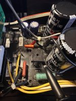
I have now isolated the PSU and here is a short clip. This jumping is present on bridge 4D4B42 and also after filter caps. Here is a picture how i'm probing positive on bridge and ground on black 0v from transformer. What i don't understand (besides alot more) is that im nog getting this jumping on the other rail supplying 81v to CN13. All caps are new Chemi-con and panasonic from Mouser and digikey. I am getting +-84v not 81v maby that is within tolorance?Check out the “The Bog Standard” thread here for a project aimed at designing a simple but good first amplifier build. You will also enjoy seeing me getting my butt kicked for some of my questionable design choices. 😀
Unless you have some extremely strange topology, the transformer center tap should be ground, which in your case are the black leads coming out of the PSU.
If possible, I would test the PSU in isolation. Disconnect the wires feeding the amplifier and probe the voltages. There’s a slight chance that the PSU itself is the issue for the current draw. Measure and probe the outputs. You may see some 50Hz ripples, but definitely not more than a volt or so with no load and there shouldn’t be any high frequency noise or oscillations.
It would be good to at least have the PSU ruled out.
Attachments
You’re at 20mV/div in AC mode, so that ripple and noise is totally acceptable.
The low frequency fluctuation is interesting, though. Put the scope in DC mode with 10V/div and a really slow time base, like 0.2s/div and the vertical to 10V/div. There shouldn’t be any big fluctuations, but it’s impossible to tell when you’re in DC mode.
84V is likely just fine. It’s an unregulated supply, so it’s dependent on your mains voltage, which can vary depending on your location. It’s usually a bit higher than the nominal voltage (230VAC in your case). At least in my experience.
I have tried my best to clean all bad traces. Using kester 40 leaded. The part witch have jumper wires is where all the transistor gather.And one more thing: Can you post a picture of the solder side of the board so we can get an idea of the quality of the soldering work? That could also tell us a lot about what may be wrong!
Attachments
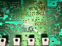
I would have binned that board faster than a paycheck disappearing on a Friday night, but it looks like you did a good job repairing it. However, your problem could very well be a short, faulty connection or open circuit somewhere in that mess. I’m assuming you’ve beeped out all the connections and checked against the schematic. The fact that the dropper resistors for the preamp are getting hot and that it’s drawing excessive current without a load makes me believe that something is going on in the preamp section. What part of the schematic does that dodgy area correspond to?
But don’t get your hopes up that it’s going to be easy. If someone manages to trash a board that bad, there’s zero chance he or she got the component values, placement and orientation right anywhere. You could be looking at a dozen faults.
But don’t get your hopes up that it’s going to be easy. If someone manages to trash a board that bad, there’s zero chance he or she got the component values, placement and orientation right anywhere. You could be looking at a dozen faults.
Is this correct?You’re at 20mV/div in AC mode, so that ripple and noise is totally acceptable.
The low frequency fluctuation is interesting, though. Put the scope in DC mode with 10V/div and a really slow time base, like 0.2s/div and the vertical to 10V/div. There shouldn’t be any big fluctuations, but it’s impossible to tell when you’re in DC mode.
84V is likely just fine. It’s an unregulated supply, so it’s dependent on your mains voltage, which can vary depending on your location. It’s usually a bit higher than the nominal voltage (230VAC in your case). At least in my experience.
I would have binned that board faster than a paycheck disappearing on a Friday night, but it looks like you did a good job repairing it. However, your problem could very well be a short, faulty connection or open circuit somewhere in that mess. I’m assuming you’ve beeped out all the connections and checked against the schematic. The fact that the dropper resistors for the preamp are getting hot and that it’s drawing excessive current without a load makes me believe that something is going on in the preamp section. What part of the schematic does that dodgy area correspond to?
But don’t get your hopes up that it’s going to be easy. If someone manages to trash a board that bad, there’s zero chance he or she got the component values, placement and orientation right anywhere. You could be looking at a dozen faults.
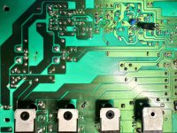
It's this part. I have gone true everthing maby 10 times. I have tested continuity between connections serveral times as well, might need to check that again. I have checkt every component to verfiy orientation and right value. Every component is checked but the emitter resistors are 0,18x2 any my multimeter will not realy read that exact, im thinking of getting a new LCR tester that test more precise. I have not removed relay to check im not sure how to and not sure if it could be a problem. There is a 18uH inductor im not able to test eather my LCE meter is not able to measure it that precise it's the one in the middle to the right L501, it should be ok.
This is the area that is getting hot.
😆I would have binned that board faster than a paycheck disappearing on a Friday night, but it looks like you did a good job repairing it. However, your problem could very well be a short, faulty connection or open circuit somewhere in that mess. I’m assuming you’ve beeped out all the connections and checked against the schematic. The fact that the dropper resistors for the preamp are getting hot and that it’s drawing excessive current without a load makes me believe that something is going on in the preamp section. What part of the schematic does that dodgy area correspond to?
But don’t get your hopes up that it’s going to be easy. If someone manages to trash a board that bad, there’s zero chance he or she got the component values, placement and orientation right anywhere. You could be looking at a dozen faults.
Just so I understand it is normal behavior for the waveform to move up and down like that? Before I replaced my main caps the waveform would actually die and come back up. Now it is a bit more steady. But if this I normal then I will let that issue pass.You’re at 20mV/div in AC mode, so that ripple and noise is totally acceptable.
The low frequency fluctuation is interesting, though. Put the scope in DC mode with 10V/div and a really slow time base, like 0.2s/div and the vertical to 10V/div. There shouldn’t be any big fluctuations, but it’s impossible to tell when you’re in DC mode.
84V is likely just fine. It’s an unregulated supply, so it’s dependent on your mains voltage, which can vary depending on your location. It’s usually a bit higher than the nominal voltage (230VAC in your case). At least in my experience.
Read my previous post again: I don’t know until I’ve seen it in DC mode with a slow time base. Right now it’s fluctuates just a few tens in millivolts, but the AC coupling could be hiding a bigger problem. But if a few tens of millivolts of fluctuations is all you see, it’s probably just your mains voltage jumping around a bit.
I don’t see a trace. Adjust the horizontal gain and offset until you see one.Is this correct? View attachment 1416384
- Home
- Amplifiers
- Solid State
- Need help with oscillating amplifier (Denon POA)