
Sorry if I keep bugging you about the jumping waveform. Considering this stable ac going into bridge rectifier it’s normal for the rectifier to leave ac fluktuation and it so few mV that is nothing to worry about? I just wan to rule out that is not causing any problem from psu to main amp board. The other rail is stable and I can’t se any jumping going on and dc looking good as well.View attachment 1416423
Measurment after transformer 58,8V
it’s replaced with:
https://www.mouser.se/ProductDetail/Texas-Instruments/OPA1642AIDR?qs=/qzd9s%2BcLd5XsvkIemKm8g==
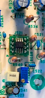
On a adapter board. Under I have one (solder side) 0.1uf CG0 type capacitor across pin 4 and 8.
https://www.mouser.se/ProductDetail/Texas-Instruments/OPA1642AIDR?qs=/qzd9s%2BcLd5XsvkIemKm8g==
On a adapter board. Under I have one (solder side) 0.1uf CG0 type capacitor across pin 4 and 8.
Attachments
The waveform fine if the fluctuations are just in the millivolt range. The BIG jumping around that's happening when you connect the amplifier is a huge issue, though. You said that the DBT was flashing, right?
I would have suggested you measure all the voltages that are indicated in the schematic, but I guess you can't since it isn't stable. I'll get back after work.
I would have suggested you measure all the voltages that are indicated in the schematic, but I guess you can't since it isn't stable. I'll get back after work.
Yes the DBT is flashing at low glow I have a 100w bulb and tried a 150w but not a 200w yet.The waveform fine if the fluctuations are just in the millivolt range. The BIG jumping around that's happening when you connect the amplifier is a huge issue, though. You said that the DBT was flashing, right?
I would have suggested you measure all the voltages that are indicated in the schematic, but I guess you can't since it isn't stable. I'll get back after work.
Yes that’s the problem I can make any measuments when main amp is connectors to CN6 and relay klicks, I can do some but 5min in my voltage drops and I need to wait. I can do some measuments when pulled but only right side of amp were output transistors are.
Yes I could try remove 501 tomorrow. Is it with testing the relay or is it probably not a problem?
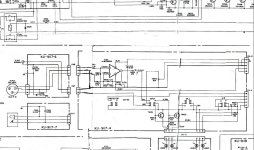
No idea TBH. You need to figure out how to separate the parts and test them in isolation. Removing IC501 should break the connection between the preamp and power amp and PROBABLY should behave well. DO NOT have anything plugged in to the outputs, as it might output some DC. And DO use a low power bulb, at least to begin with. You just want to break the circuit down little by little until i stops doing crazy things. Then you can start taking useful measurements. But it's not easy, since everything in an amplifier depends on everything else, including itself.
If you're successful in removing the crazy oscillations, you can start testing the preamp in isolation, i.e. feeding in a signal and make sure it comes out in the other end.
If you're successful in removing the crazy oscillations, you can start testing the preamp in isolation, i.e. feeding in a signal and make sure it comes out in the other end.
By the way, we’ve only talked about one channel. Do both channels behave the same? (Or this a mono block? I’m not familiar with it)
Yes I’ll get back to youNo idea TBH. You need to figure out how to separate the parts and test them in isolation. Removing IC501 should break the connection between the preamp and power amp and PROBABLY should behave well. DO NOT have anything plugged in to the outputs, as it might output some DC. And DO use a low power bulb, at least to begin with. You just want to break the circuit down little by little until i stops doing crazy things. Then you can start taking useful measurements. But it's not easy, since everything in an amplifier depends on everything else, including itself.
If you're successful in removing the crazy oscillations, you can start testing the preamp in isolation, i.e. feeding in a signal and make sure it comes out in the other end.
Correct it’s a mono block.By the way, we’ve only talked about one channel. Do both channels behave the same? (Or this a mono block? I’m not familiar with it)
The hot resistors power the opamps that were changed for different types. 501 moves the rails about 551, which isn't DC offset, but bias control.
This: https://www.ti.com/lit/ds/symlink/opa1642.pdf?ts=1738596522284&ref_url=ht
Swapped for this: https://www.ti.com/lit/ds/symlink/opa1656.pdf
Neither of these numbers are on the drawing. Others in the range (71v rails) use an 082 for both, while this amp uses an 082 for 501, and a different one in the second feedback loop.
The 1656 might not be suitable. I can't say.
The fet swap at the very input ids also something I can't look at, as I don't know what used to be there. However, there are test points around it.
I have, on occasion, taken the power off the main rails, to allow me to power other areas that otherwise wouldn't stay on. This would mean no red, no black, no blue. Then shove in relay 501, which yes, could be dirty.
I take no responsibility for this advice, and would likely achieve this with wire across the relay, and using the power switch at the wall to test a couple of points, then rest. As you know it's a bit hot, where the opamps are fed. Making voltages there a good start. Or just go left to right.
Keep in mind that ic501 won't have the correct differential input, so it's output might be off. Perhaps not though, as it's looking for nothing.
Edit, the red and blue are fuse 001 and 002, and leaving the black seems reasonable.
Do remember this pre section still has enough volts to make you jump. Right into your grave.
Last edited:
Hello! So I have made som progress actually found a zener diode at D507 to be fault, it is now replaced and i am getting out of protection and amp is steady and i'm able to do some readings BUT some positions i'm causing major oscillation when probing around. Specially around the OP-amps.

I have done some measuremens with my scope and if i'm not doing it wroing i'm ablte to find a bad noisy freq at around 7MHz. When i dissconnect CN6 this noise is gone. So what can a next step be?

I have done some measuremens with my scope and if i'm not doing it wroing i'm ablte to find a bad noisy freq at around 7MHz. When i dissconnect CN6 this noise is gone. So what can a next step be?
Ok. Just wondering because it dissapears when i remove CN6. It is so wierd somethime when i power up i come off protection mode and DBT goes out and i got 7mV dc on output. Then sometimes my DBT lights up a little bit and i get 300mV on output then next time it's okay gain.
As soon as i connect input DBT ligts up, with a 1K signall. Removing input and i'm back to stable. Fun! 2 pics of my output:


As soon as i connect input DBT ligts up, with a 1K signall. Removing input and i'm back to stable. Fun! 2 pics of my output:
- Home
- Amplifiers
- Solid State
- Need help with oscillating amplifier (Denon POA)