It's hard to test the relay in cirquit becuaise its hard to reach. I will se if i'm able somehow. Maby i can mount some jumper cables to the switches and test them when amp powered on?
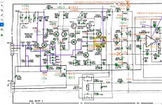
I got strong 15v now when IC's removed. So the green ones are new measuments and the green dots are tested OK. I cot a hold of a new LCR meter witch made it possible for me to test L501 18uH and it is good! Im still having no clue why i'm getting 300mV on TR500 and TR501. And also the 360mV i'm getting at TR507? I pulled both 507 and 508 and they read OK!

I got strong 15v now when IC's removed. So the green ones are new measuments and the green dots are tested OK. I cot a hold of a new LCR meter witch made it possible for me to test L501 18uH and it is good! Im still having no clue why i'm getting 300mV on TR500 and TR501. And also the 360mV i'm getting at TR507? I pulled both 507 and 508 and they read OK!
Is that with the bias turned all the way down?
What happens at the output when you turn the bias up? Check both DC voltage and waveform.
What happens at the output when you turn the bias up? Check both DC voltage and waveform.
Did you replace D503 and D504 by any chance or are they original? If they have a higher forward voltage, you’ll get a higher bias current through TR507 and TR508. This also increases the voltage drop across the resistors, which is what you’re measuring. If the transistors were replaced, they might have a different BE voltage drop and/or hFE, which can also affect things. 360mV across the 22ohm resistor implies an idle current or 16mA. I don’t know if that’s enough to cause any problems, but it’s definitely out of spec.And also the 360mV i'm getting at TR507
Looking at your measurements, the diode drops look ok, so I suspect that the transistors have different parameters from what the designers had in mind. What were the originals and what were they replaced with? Worth looking into, but I’m not sure this is what’s causing the catastrophic oscillations you’re seeing.
Yes, i was about to check this and before i do that i don't like what i see on these measuments. This is on ouput from amplifier board. Measuring wrong?Is that with the bias turned all the way down?
What happens at the output when you turn the bias up? Check both DC voltage and waveform.
Attachments
Both are replaced with 1N965B and orignals where HZ15-2, 14.8 nominal value. I was able to sort out two 14.8 and the other ones are 14.7 i though that it couldnt be that big of a differense 0.1v and be a reason for my problems, but hey maby?Did you replace D503 and D504 by any chance or are they original? If they have a higher forward voltage, you’ll get a higher bias current through TR507 and TR508. This also increases the voltage drop across the resistors, which is what you’re measuring. If the transistors were replaced, they might have a different BE voltage drop and/or hFE, which can also affect things. 360mV across the 22ohm resistor implies an idle current or 16mA. I don’t know if that’s enough to cause any problems, but it’s definitely out of spec.
Looking at your measurements, the diode drops look ok, so I suspect that the transistors have different parameters from what the designers had in mind. What were the originals and what were they replaced with? Worth looking into, but I’m not sure this is what’s causing the catastrophic oscillations you’re seeing.
It's possible as you say, the old ones were TR508 2SA1321 replaced with KSA1381ESTU and the TR707 2SC3334 replaced with KSC3503DSTU and both should be good replacment transistors.
That’s 50Hz hum and not oscillation. You definitely don’t want that much hum, but it could be because things are left floating when you removed the opamp. That’s not what’s causing the amp to draw a lot of current.
You said you dialed up the voltage across the bias test points to 10mV? That’s 4*(0.01/0.18)=0.222A, which is 80*0.222=17.76W. That might be enough to make the voltage drop significantly over across the DBT and light it up a bit.
Are you really sure it’s oscillation you see and not just the effects of a hefty bias? I would start by keeping the bias very low until you have it working.
Here is a picture of when bias is set to 0,16mV. Probe on output from amplifier.

Here is just before im setting bias.

Here is just before im setting bias.
At this point amp is OK with DBT
So what’s the issue then? I wouldn’t worry too much about the hum at this point, since you don’t have the opamps hooked up and the input is basically floating.
You could break the connection between the preamp and power amp and put the opamps back and see if it stays stable.
Maybe you should shift focus to the preamp?
The problem start when i start hitting above 1mV and the the service manual state 8mV -+1mV. With or without OP-aps. How does the DBT effect my bias setup here? Maby i'm hitting higher than 1mV without DBT?
What problem? I’m not sure I see a problem in the traces you showed me. You have some hum and minor high frequency noise with about 64mV amplitude. That’s something you need to address at some point, but it’s not catastrophic. What am I missing?The problem start when i start hitting above 1mV
Ok, you are prob right! I'm leaving bias at 1mV and i will insert the OP-amps tomorrow and se where i'm at. What do you think?

Input(not able to go lower on my phone)

Output on resistor R533. Of course this is with volume turned upp maby 5%.


Output on resistor R533. Of course this is with volume turned upp maby 5%.
Last edited:
- Home
- Amplifiers
- Solid State
- Need help with oscillating amplifier (Denon POA)