Second question about bias. I put a 2k2 trim pot instead 1kohm that was in this kit and now I can't set the bias more than 8mA. So maybe I should put 1kohm back?
I would look first in the Vbe multiplier transistor, because the bias is definitely not working. Usually, people follow the layout and install the transistor the wrong way. Follow the schematics and the transistor pinout instead.
When you fix that you may find that the other problem is also gone.
Last edited:
OK, thank you.
Today I checked Vbe multiplier transistor and everything was OK just like in schematic. But I've noticed that one resistor is 1k5, as labeled on PCB, althought on the picture of real NAP it looks like 2kohm (according to color chart). Have changed it and it allowed me to set proper bias (it was about 6mV on emmiter resistor).
Now bad things. The hum remains the same. But I've notice that it totaly disapears when I toucing some places on PCB with probes of my multimeter. I marked this places in red circle in attaced schematic. Same thing in both chanels, even when I touched the body of this resistors by fingers. In this case amp is workin good, deth quiet and sound is goit on.
Now the worse thing. I've shortened something and ZTX753 is blown away. Have to order another one. 🙁
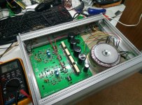
Also post the picture of my build. Hope you help me.
Sory for my english, hope you'll got the thing.
Today I checked Vbe multiplier transistor and everything was OK just like in schematic. But I've noticed that one resistor is 1k5, as labeled on PCB, althought on the picture of real NAP it looks like 2kohm (according to color chart). Have changed it and it allowed me to set proper bias (it was about 6mV on emmiter resistor).
Now bad things. The hum remains the same. But I've notice that it totaly disapears when I toucing some places on PCB with probes of my multimeter. I marked this places in red circle in attaced schematic. Same thing in both chanels, even when I touched the body of this resistors by fingers. In this case amp is workin good, deth quiet and sound is goit on.
Now the worse thing. I've shortened something and ZTX753 is blown away. Have to order another one. 🙁
Also post the picture of my build. Hope you help me.
Sory for my english, hope you'll got the thing.
Attachments
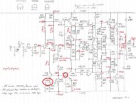
The fact that touching the current sources for the input stage with meter probes kills the noise, does suggest oscillation.
However, is the noise actually hum, where there is a dominant, low frequency? Oscillation (AKA instability) seldom has much low frequency or audible content at all. If it is hum, you should check that your ground wiring and connections are correct. For example, there should not be multiple connections between the chassis and/or between the top and bottom copper layers of the PCB. The PCB mounting bolts could possibly cause a problem by forming a short there. As you may be aware, the original PCB "floats" on rubber mounting posts, so this isn't possible.
Also, the ground connection for the preamp inputs is designed for a single ground wire - not the normal type where there are are separate grounds for the chassis and each signal lead, as you find where RCA connectors are substituted. This problem and a solution for use with the NAP 152 clone kit, has been discussed here recently.
BTW, what is the material you are using for the bottom of your case, Azatto? I can't be certain from the pic. but it doesn't look like aluminium or other suitable heat conductive metal, which you definitely need for the heatsink.
Member
Joined 2009
Paid Member
But I've notice that it totaly disapears when I toucing some places on PCB with probes of my multimeter. I marked this places in red circle in attaced schematic. Same thing in both chanels, even when I touched the body of this resistors by fingers. In this case amp is workin good, deth quiet and sound is goit on.
You don't say if you have correct currents and voltages in this area. Are the current sources working as expected? What are the transistors installed there? Are they very high gain devices?
Same as before: first check the surrounding components, values, transistors pinout. Measure the actual currents. Are they close to 4mA and 10mA?
... I don't have practical experience with this type of 2-transistor feedback current source, but if there is feedback there may be oscillation. Adding some capacitance with your fingers or DMM probes kills it.
Current source - Wikipedia
The end of this article shows similar schematic but they added some base stopper. Not a bad idea to try few hundreds ohms in the base of TR3A, if anything else checks OK and you still have the oscillation.
Yes, transistors in current source is high gain MPSA18 (came with the kit).
Voltages seemed to be allright, as in schematic. Haven't measured curents.
I have ordered onother pair of ZTX753, so later i'll try one more time🙂
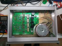
The bottom of chassis is annodised alluminium. You can see sanded area under output transistors and near transformer.
I also ordered plastic spacers to mount schassis.
One more time thanks to everybody for your opinion and responce.
Voltages seemed to be allright, as in schematic. Haven't measured curents.
I have ordered onother pair of ZTX753, so later i'll try one more time🙂
The bottom of chassis is annodised alluminium. You can see sanded area under output transistors and near transformer.
I also ordered plastic spacers to mount schassis.
One more time thanks to everybody for your opinion and responce.
Yes, transistors in current source is high gain MPSA18 (came with the kit).
I would avoid high gain devices there. But, as I said, I don't have practical experience with this type of current source.
I wonder if this amp would benefit from having the output resistor (0.22r) wound with an inductor like the Nap140 clones have, to help with stability?
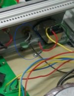
It is not a capacitor, it's thermistor going to fuse holder.This cap you have.. is it from the mains power to chassis?
What rating is it?
I'm going to change transistors in current sourse to MPSA06 as shown in schematic.
It is not a capacitor, it's thermistor going to fuse holder
Cool, hard to tell from the pic.
Greetings dear community. Looking at the NAP-200 scheme, I always have a question: from what considerations have changes been made to the nominal values in the high-frequency and phase-correction circuits, as compared to the conventional NAP-140 and 250 circuitry?
It is possible that in the case of generation with a low-frequency origin, it is necessary to introduce a decoupling over the power buses in the form of RC filters separating the input stages of the amplifier from the output stage.
I hope that the Gareth "TGMC project" has not yet lost relevance, probably due to lack of free time.
Member
Joined 2009
Paid Member
I haven’t given up on that project, but it’s not a Naim clone, rather something a bit different so for those chasing the Naim sound thingy you’ll be better off with one of the eBay boards.
OK, thank you.
Today I checked Vbe multiplier transistor and everything was OK just like in schematic. But I've noticed that one resistor is 1k5, as labeled on PCB, althought on the picture of real NAP it looks like 2kohm (according to color chart). Have changed it and it allowed me to set proper bias (it was about 6mV on emmiter resistor).
Now bad things. The hum remains the same. But I've notice that it totaly disapears when I toucing some places on PCB with probes of my multimeter. I marked this places in red circle in attaced schematic. Same thing in both chanels, even when I touched the body of this resistors by fingers. In this case amp is workin good, deth quiet and sound is goit on.
Now the worse thing. I've shortened something and ZTX753 is blown away. Have to order another one. 🙁
Also post the picture of my build. Hope you help me.
Sory for my english, hope you'll got the thing.
Hi,
Congratulations on the quality of the build - it looks brilliant 🙂
The only thing I noticed from your pictures was that you have installed the small smoothing cap and one of the diodes for the external power supply back to a pre-amp, but you are not using the external supply, so I don't think they are needed at all.
Is there any possibility that the star earth pattern on the PCB is seeing them as being in circuit?
Not sure it would make any difference to Hum but just a thought.
Looking at a nap200 clone. Posted a build up scheme here
Noob kit amp question
Anyone care to take a quick look to see if the chosen parts are compatible?
Thanks in advance.
Noob kit amp question
Anyone care to take a quick look to see if the chosen parts are compatible?
Thanks in advance.
Cable obligato!
I am not sure that all builders of Naim clones know this. Naim amps, especially older models that are often cloned, are designed in such way that loudspeaker cable is part of the amp circuit and the cable provides necessary stability to the amp. Proper Naim loudspeaker cable should have these properties in order that the amp works stable:
1.3 - 1.5microHenries per metre (Loop)
MAX 20picoFarads per metre
About 25milliOhms per meter (loop)
MIN Length 3.5 metres
The only cable that I know of having these specs is Naim NACA 5 (or older NACA4) cable.
Also note there is a specific warning not to use Litz type high capacitance cables (like Kimber).
Actually, even Zipcord or lamp flex, figure-8 flex etc. goes close enough to the above figures. Suitable cable capacitance and inductance figures are not unique to NAC A4 or 5 cables, their use simply ensures a known standard of performance and reliabilty. Of course, the reactance values are proportional to length, hence Naim's specification of a 3.5-5m length. NAC A5 was a forced replacement for obsolete NAC A4 but not well liked because a stiffer grade of PVC is now used for the sheath.Cable Obligato
As Ivan may be suggesting, it would thus be a mistake to fit cables that have widely spaced conductors, like the many exotic grades of copper twin flex that sell for astronomical prices. I have used and sold some good ol' 10A mains twinflex that has proven to work stably on many of the old NAP and NAIT models and a few newer ones too.
RFI is also related to using long lengths of speaker cable. This is sensitivity to radio, TV transmissions, EMI etc. and I have witnessed strong breakthrough from nearby transmitters and road traffic with several Naim models over the years and this was usually reduced or eliminated by using a minimal 2m cable length and fitting a small inductance of about 3uH inline to compensate. Sometimes, simply rolling up any excess cable did the job 😉
0,75mm2 Lampflex (which is one of my favorite speaker cables) has capacitance of some 40-50pF. That's twice what is recommended. Unfortunately I don't know specs for inductance but I doubt that it is as high as needed.
Unfortunately, all other speaker cables that have published specs are far from specs needed for Naim amps. As I said, I did some research concerning speaker cable specs and did not find anything remotely similar to Naim specs. I did not find anything with so low capacitance, so high inductance and so low resistance. Many Naim users disregard company's speaker cable recommendations which turn out to be "buy Naim speaker cable".
Unfortunately, all other speaker cables that have published specs are far from specs needed for Naim amps. As I said, I did some research concerning speaker cable specs and did not find anything remotely similar to Naim specs. I did not find anything with so low capacitance, so high inductance and so low resistance. Many Naim users disregard company's speaker cable recommendations which turn out to be "buy Naim speaker cable".
- Home
- Amplifiers
- Solid State
- NAP-140 Clone Amp Kit on eBay