Can you read directly on the 3 pins on the reg itself ?
You see the left red circle in the circuit diagram is the output side... that can not have 23 volts on it.
Measure it now on the reg, all 3 pins, carefully.
You see the left red circle in the circuit diagram is the output side... that can not have 23 volts on it.
Measure it now on the reg, all 3 pins, carefully.
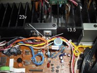
Must have been a bad solder joint where the flat cable connects to the reg. I just re-flowed the solder joint, and get 23.4V at Pin1, 1.3V at the middle pin, and 13.2 at the rightmost pin.
Sounds like this was worth missing a few ZZZs over.🙂
But still no tuner...
What's next?
Sounds like this was worth missing a few ZZZs over.🙂
But still no tuner...
What's next?
OK those voltages are spot on.
I take it you still have the output of the reg disconnected ?
What I would do given limited test gear is this.
1. Don't alter anything but now add a 60 or 100 watt mains filament bulb in series with the incoming mains supply to the unit. (There is no point blowing more resistors etc, it's not proving anything other than a fault exists).
2. Switch on and make sure the unit powers up with the bulb glowing dimly.
3. Switch off and reconnect the output of the reg.
4. Switch on again and if the bulb lights brightly then there is a short on the rail supplied by the reg. The bulb should hopefully offer a non destructive way of faultfinding.
Can you read directly on the 3 pins on the reg itself ?
You see the left red circle in the circuit diagram is the output side... that can not have 23 volts on it.
I'm assuming that the left red circle is pin1 at CN41, and there is 23.4V there.
Measure it now on the reg, all 3 pins, carefully.
Remember I can not see the actual unit... that makes it much more difficult for me 🙂
You have to now follow the connection from the reg itself to the main board. That is the 13.5v rail.
To just wire up the output pin and switch on is just going to blow the resistor again so we have to find (as above) some other way of trying to work on it.
You have to now follow the connection from the reg itself to the main board. That is the 13.5v rail.
To just wire up the output pin and switch on is just going to blow the resistor again so we have to find (as above) some other way of trying to work on it.
Gotta go... I'll look in later.
Rig the bulb up. Solder a couple of long wires to it and put it safely out of the way.
If you remove the main fuse in the unit you can then solder the wires across the fuseholder.
Rig the bulb up. Solder a couple of long wires to it and put it safely out of the way.
If you remove the main fuse in the unit you can then solder the wires across the fuseholder.
OK those voltages are spot on.
I take it you still have the output of the reg disconnected ?
Yes, it is.
What I would do given limited test gear is this.
1. Don't alter anything but now add a 60 or 100 watt mains filament bulb in series with the incoming mains supply to the unit. (There is no point blowing more resistors etc, it's not proving anything other than a fault exists).
2. Switch on and make sure the unit powers up with the bulb glowing dimly.
3. Switch off and reconnect the output of the reg.
4. Switch on again and if the bulb lights brightly then there is a short on the rail supplied by the reg. The bulb should hopefully offer a non destructive way of faultfinding.
OK, I'll make up a dim bulb tester tomorrow. About time I had one. Should that be connected to where the AC actually comes into the unit or after the main filter caps?
Attachments
Doesn't matter where for this as we know it's a fault on the secondary side.
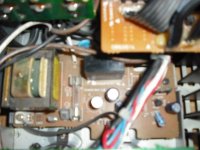
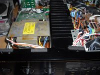
Where ever is easiest. I can't tell just by looking at the pictures... for example is that fuse in the incoming supply or does it just feed what looks like a small auxilliary transformer.
Just seeing that though I'm having second thoughts. If the voltage to the small tranny dips then the unit may not power up at all... if it uses a relay for standby etc. We can always try it, won't harm anything.
Might be better if you can put the bulb in the AC feed to the primary of the big mains transformer only if thats easy to do.
OK, made up the Dim Bulb Tester per Googled response from the Antique Radio site. Hooked up a wire from the DBT to (what I think is) the transformer mains, and the 100 watt bulb glowed bright for a brief moment, then settled down to about half bright. But then I heard what sounded like a relay click open and closed a couple of times, so I stopped. I did not reinstall the pin3 leg from the reg, since I was unsure if the relay reaction was safe and didn't want the relay to keep opening and closing. I got the same response when I hooked the receiver directly to the DBT, but the relay clicking was a little louder and more pronounced.
I studied the schematic to see where the 13 volt rail goes to, and it might be to CN35, which is that twisted blue wire that connects to the board right next to the AG3 glass fuse. That appears to go to one side of the transformer and has the note on the schematic "to tuner transformer". Is that correct? There was no voltage at CN35, but the reg was not completely connected.
I studied the schematic to see where the 13 volt rail goes to, and it might be to CN35, which is that twisted blue wire that connects to the board right next to the AG3 glass fuse. That appears to go to one side of the transformer and has the note on the schematic "to tuner transformer". Is that correct? There was no voltage at CN35, but the reg was not completely connected.
Attachments
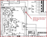
Looking at the circuit if you remove fuse F901? (bit blurry) as shown and fit the bulb in place of the fuse. That allows the standby circuit to receive full mains voltage and so should power up OK. If the bulb glows fairly bright that is because the main amps are drawing current.
Switch on... does the 13 volts appear OK on the reg (still with its output isolated). What is the voltage at the input to the reg now ? It will be lower than the 22 volts before. If its below about 17 then I would suggest fitting a slightly higher wattage bulb if possible.
[Depending on the outcome of this we may also have to turn down the quiescent current in the power amps to get the unit drawing as little power as possible from the mains]
What we do now is switch off and reconnect the regulator.
Connect your meter on volts to the output of the reg. Switch on... is the bulb very bright. Yes or no ? Whats the voltage ? Switch off immediately.
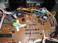
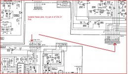
You then need to isolate items on the 13 volt rail to see what is pulling it down such as these two points here. Isolate these pins one at a time and repeat the above.
Switch on... does the 13 volts appear OK on the reg (still with its output isolated). What is the voltage at the input to the reg now ? It will be lower than the 22 volts before. If its below about 17 then I would suggest fitting a slightly higher wattage bulb if possible.
[Depending on the outcome of this we may also have to turn down the quiescent current in the power amps to get the unit drawing as little power as possible from the mains]
What we do now is switch off and reconnect the regulator.
Connect your meter on volts to the output of the reg. Switch on... is the bulb very bright. Yes or no ? Whats the voltage ? Switch off immediately.
You then need to isolate items on the 13 volt rail to see what is pulling it down such as these two points here. Isolate these pins one at a time and repeat the above.
Attachments
Mooly,
Greetings once again and Happy New Year.
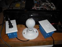
I built a Dim Bulb Tester, so I don't have the exact bulb set-up you described. So, what I did is take an old lamp cord and plugged that into the DBT to feed 120V (verified with DMM) to the fuse holder. The bulb does not light at all, and the reg shows about .75 volts.
Hopefully this doesn't complicate things. Would a simple bulb and socket be preferable?
Greetings once again and Happy New Year.
I built a Dim Bulb Tester, so I don't have the exact bulb set-up you described. So, what I did is take an old lamp cord and plugged that into the DBT to feed 120V (verified with DMM) to the fuse holder. The bulb does not light at all, and the reg shows about .75 volts.
Hopefully this doesn't complicate things. Would a simple bulb and socket be preferable?
Attachments
Hi and happy new year,
It's getting very complicated all this. It should all behave pretty much as before with the bulb at least glowing, so it sounds as though something isn't wired up right.
The bulb just goes across the fuseholder.
It's getting very complicated all this. It should all behave pretty much as before with the bulb at least glowing, so it sounds as though something isn't wired up right.
The bulb just goes across the fuseholder.
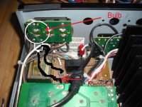
There are two fuses. The one with the clips is 901, and is a 6 amp fuse. The one you drew lines to is a 0.5 amp fuse, and is F902.
I re-did the tester and hooked it up to the same fuse (901) as before. The thing lights up as you said, and the reg Pin1 is now 16.7V, and the pin 3 (isolated) is still 13.3V.
Hopefully you get this before you have to go.
I re-did the tester and hooked it up to the same fuse (901) as before. The thing lights up as you said, and the reg Pin1 is now 16.7V, and the pin 3 (isolated) is still 13.3V.
Hopefully you get this before you have to go.
That sounds OK, so what you need to do now is work through the tests in post #91 by first reconnecting the reg and seeing what happens.
The bulb should allow you to work on it non destructively. Make sure the regulator doesn't get too hot so try and make measurements quickly until you are sure nothings overheating.
The bulb should allow you to work on it non destructively. Make sure the regulator doesn't get too hot so try and make measurements quickly until you are sure nothings overheating.
Eureka!
Mooly,
So far so good! The tuner works! It can be tuned up and down and the signal meter works, too.
Thanks again for your patience and expertise! I'm sure it's not easy to guide a newb through circuit troubleshooting. But it did break the ice for me in an area I have not much experience in.
I have the IC-N15s on order to replace the temporary resistor "fuses", which I have now taped over.
A few tuner issues are now visible. One is that the tuner won't auto-tune. Early on I was given the advice to adjust L305 to 0.0V at TP-1 in the event that was causing the tuner issue. Unfortunately it won't adjust fully, and it's a two-pin test point. One pin goes down to 1.07V and the other remains at 6.25V. If shorted together they measure 6.25V.
The troublesome part of the auto-tune not working is that when the auto-tune button is pressed, there is a decent sized pop sound heard from the speakers, and the tuner mutes fully. When the button is pressed again, the tuner unmutes and that sound is heard again. It also runs up and down the 'dial', (and the signal strength meter changes) but does not lock in on any station. I could understand that FM muting would kick on during the auto-tune, but I'm wondering if that pop is normal. I would think it isn't. It doesn't happen on AM, only on FM. I've checked all the ribbon cables which had to be removed and reinstalled every time the board had to come out, and they are all now fine.
Maybe now would be the time to move this thread over to the analog tuner forum.
Thanks again for your help. Fixing the tuner on New Years Day is a great way to start the year.
Well that's great news... I know there were a few little "moments" along the way that aren't in the thread... but we got there in the end.
So the tuner... yes maybe a new thread would be a good idea. It's so specialised a field, and needs the right equipment. When adjusting be aware ferrite cores break and crack so very easily too, and so they should always have the proper (as in a non ferrocious, or non ferrous even lol) trimmer.
Just quickly looking at the manual L305 is adjusted by measuring between the test points, not from ground to them. This will have to be done under specified conditions too with regard to RF signal, deviation etc. Page 40 of manual in the block diagram shows pin 12 of IC302 as possibly being the trigger signal to show that a station has been found. Just looking very quickly it appears that the signal here is fed into pin 32 of U506 to stop the tuning voltage sweeping (and so stopping on the station) and fed to the display/driver to indicate "lock". Worth monitoring that line and seeing if the voltage changes state.
Thanks again for the discernment. When measuring between the test pins I got 5.16V, still far in excess of the 0V +- 20 mv.
Ah, so that box-like structure I was trying to adjust is a ferrite core. I used both a chopstick or a plastic fork tine shaved down to fit the notch in it. And quite possibly it might be cracked (or have been cracked by adjusting), as it did not move easily, and I noted that downward pressure easily changed the value.
In any event, the lack of auto-tuning isn't a problem for me - there are only a couple of stations I listen to. I'm much more concerned that the popping noise made when the auto mode button is engaged might be a sign of a different issue, maybe a bad component.
In addition, when I engage station memory by pressing a pre-set, the display advances to that station but the tuner goes into auto mode and mutes. The auto mode must be pressed again in order to un-mute it, which then makes another pop. This popping noise doesn't happen on AM - only FM.
So I figure something must be amiss, and would probably only get worse with time. I checked all the ribbon cable that had to be unhooked before the video/control board could come out. There were a few worn and bent leads that required trimming the cable, but it seems to be physically OK now, with all the wires connected to the right places. It might behoove me to disassemble the front again to examine the cables to check out where they are soldered into the display pcb. Since the tuner didn't work when I got it, no way to know if this was pre-existing to the ribbon cable movements or not.
It seems suspicious that the cause of this could be a crossed wire, but so far I've corrected all of that, at least as much as I can tell. Maybe the ICs on that board are confused and need the Mooly aluminum foil trick?
I've started another thread in the analog section, BTW.
Last edited:
Amazing!
I decided to try adjusting the L305 again. This time I did get it about as close to spec as I think I can - and the issue with popping has stopped, and the auto mode works.
I'm amazed, thrilled, and relieved.
Now just to replace those resistor fuses with the ICPs, and then done!
Thanks again for all your support!
- Status
- Not open for further replies.
- Home
- Source & Line
- Analog Line Level
- Nakamichi TA4A tuner has no output