Thanks Mooly.
Yep, crystal (pin 2+3 ic 602) is spot on, gives me a good sanity check that cro and i are working together.
I was going to snapshot all pins, I did probe them all, but most were as you say low level noise.
mostly under 200mv.
And none did anything of note when pushing fp buttons.
As I measured I pushed the various fp buttons and made notes and snaps of any differences.
Im glad you mentioned pin34, I though it was odd, looks like a secondary smaller square wave superimposed..
New measurements.......
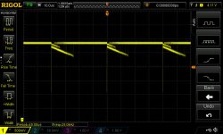
R602 removed, measuring pin 34.
picture 23 = fm selected.
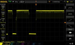
picture 24 = am selected (just random noise)
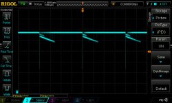
picture 26 - fm selected and doing an 'auto seek'
picture 26 is the only one that looks even vaguely like what I'd call a square wave.
EDIT, re possible chip failure, dont forget I had to replace the fuse in the 30v rail and do other repairs to that 30v supply as well.
I'd wonder if the rail failure (due to gorilla snot damage) may have sent something ic 602 didn't like ?
Did ic 602 take out the supply fuse, or did the supply failure take out ic602 that then took out the 30v rail fuse.........
Yep, crystal (pin 2+3 ic 602) is spot on, gives me a good sanity check that cro and i are working together.
I was going to snapshot all pins, I did probe them all, but most were as you say low level noise.
mostly under 200mv.
And none did anything of note when pushing fp buttons.
As I measured I pushed the various fp buttons and made notes and snaps of any differences.
Im glad you mentioned pin34, I though it was odd, looks like a secondary smaller square wave superimposed..
New measurements.......
R602 removed, measuring pin 34.
picture 23 = fm selected.
picture 24 = am selected (just random noise)
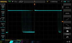
picture 26 - fm selected and doing an 'auto seek'
picture 26 is the only one that looks even vaguely like what I'd call a square wave.
EDIT, re possible chip failure, dont forget I had to replace the fuse in the 30v rail and do other repairs to that 30v supply as well.
I'd wonder if the rail failure (due to gorilla snot damage) may have sent something ic 602 didn't like ?
Did ic 602 take out the supply fuse, or did the supply failure take out ic602 that then took out the 30v rail fuse.........
Attachments

Last edited:
I can't see IC602 taking the fuse out but failure modes and the analysis are weird sometimes.
The shot of it doing the auto seek. It looks vaguely OK-ish in that it looks like a full amplitude signal with a variable duty cycle.
If you load pin 34 to ground with something like 10k, does it kill the waveform ?
The shot of it doing the auto seek. It looks vaguely OK-ish in that it looks like a full amplitude signal with a variable duty cycle.
If you load pin 34 to ground with something like 10k, does it kill the waveform ?

Its hard to say for sure what is going on here. The signal you have on pin 34 (last picture) is unvarying when you try and tune ?
Another line of attack... disconnect R650 that feed the tuning volts to the front end. Wire a 10k or 22k pot or preset across the 30 volts line and connect the wiper to R650 so that you can vary the tuning voltage manually. Set the tuner up for FM mode and see if you can pick up any stations.
If you do hear audio then it looks as if something is amiss with either the uP or the prescaler. We've scoped the prescaler and it has output but that doesn't mean that its correct... there could possibly be a problem with the division ratio internally.
Heya.
Yes thats correct, manually or using the seek function, tuning has no effect on pin34.
I shall try your second attack in the morning and report back.
as always, I really appreciate your time and effort 🙂
Yes thats correct, manually or using the seek function, tuning has no effect on pin34.
I shall try your second attack in the morning and report back.
as always, I really appreciate your time and effort 🙂
Hm.
Well sorry but I'm over it. I'm announcing the patient as 'zombie' status. (Half works)
amp and all other controls work, tuner is dead.
Wired in a pot as suggested to simulate 0 - 30v vt feed to the tuner.
nudda, zip, zero.
verified voltage variation to the vt line, yup.
verified all power supply voltages to the logic and tuner cards, yup.
Retried the 'touch the crystal trick' on the tuner card.
Now that fails where originally it did work
Seems every time I find and fix something, something else goes mammaries up.
So think ill just close it up, and walk away quietly.
Every now and then, you get a dog. And this is one of them......
I'm sure it can fixed. But it's taken more time and effort than I can afford.
So Mooly, I thank you deeply for your time and effort.
But it's time for me to walk away.
OK, no problem. It sounds like that power supply problem has probably done some damage at the front end. Its all good fault-finding experience though 🙂
I was thinking its all related.
The blown fuse in the 30v line is 2 amp. 30v x 2a is decent amount.
Yes, was all good learning for me and I seriously appreciate your time and help.
Hopefully all this extra info will help the next person.
Owner doesn't want to spend a great deal on the tuner side of things as he has other tuners.
So as much as I'd like to finish this unit (I have a later RE2 so I'm biased).
Cust is just happy to have the amp section working.
Such is life..
I have but one last question.
Why is this thread in the digital section ??
The original poster thought that because it was a digitally synthesized tuner, this is where it should go.
I read the posts, not so easy to fix a tuner like these, especially if you do not have the proper test equipment like a RF SG and a scope.
I have a Crown FM1 (got it for cheap) that has a dead GI controller, impossible to find the part. I managed to get it to work with a multi-turn pot connected to the Vt supply, to provide the tuning voltage to the varactors in the FE. It is a good test method to separate the control from the RF tuning/demodulation section.
Yes, was all good learning for me and I seriously appreciate your time and help.
Hopefully all this extra info will help the next person.
You're very welcome, and thanks for the kind words 🙂
I have but one last question.
Why is this thread in the digital section ??
perhaps a mod could move it across ?
I couldn't do it back then, but I can now 😀
The original poster thought that because it was a digitally synthesized tuner, this is where it should go.
Its a bit 50:50. We've gone through PSU's and so on. On balance its probably classed more as an analogue product in the scheme of things.
The original poster thought that because it was a digitally synthesized tuner, this is where it should go.
Ahh fair enough. I guess 😉
I read the posts, not so easy to fix a tuner like these, especially if you do not have the proper test equipment like a RF SG and a scope.
Thanks, that makes me feel better about my limited tools and abilities. If nothing else I got a nice scope and some knowledge out of this. 😀
I have a Crown FM1 (got it for cheap) that has a dead GI controller, impossible to find the part. I managed to get it to work with a multi-turn pot connected to the Vt supply, to provide the tuning voltage to the varactors in the FE. It is a good test method to separate the control from the RF tuning/demodulation section.
And if you ever find another FM1, it'll have the same fault.....
You're very welcome, and thanks for the kind words 🙂
Truer words I have not spoken.
Without your help I'd most likely be really bald, or unsure if i've told the cust the truth or not.
I couldn't do it back then, but I can now 😀
Its a bit 50:50. We've gone through PSU's and so on. On balance its probably classed more as an analogue product in the scheme of things.
I just reasoned that as the main part is the amp section, that it seems more 'analogue' to me..
Actually, with that logic, it could be argued it should go in 'Pass labs' due to the 'Stasis' tech 😛
Hello, sorry to resurrect an old thread but I am trying to fix the tuner on my Nakamichi SR-40 (the Japanese variant of the SR-4).
Let me know if I should just create a new thread instead.
I have the same problem: I get no signal, no reception, and auto-tuning just searches up and down the frequency range. "Lock" is always lit.
I tried a few of the things mentioned here: VT is +30VDC. I noticed it doesn't change as the frequency range changes, don't know if maybe the SR-4 tuner operates a bit differently from the TA-4. Doing the antenna test on the single blue filter cap close to the 1235 chip didn't change the sound. But I don't hear anything at all, so maybe a voltage line is going down somewhere? Is there another voltage line I should check? There's one labelled +15V next to the pin for muting. This measures close to 0v, could this be the issue? Then again I don't know if the +15V should be high only when the muting function is active.
I know I'm getting ahead of myself here, but since this is the Japanese model I want to change the frequency reception range to North American frequencies. Since the chips are all the same that should be fairly straightforward, but I'm having trouble identifying what component is responsible for this. Don't even know if this would be on the FM board or the logic board.
I really don't know on this but think you have your work cut out for this one.
Its one thing having a possible hardware fault, but trying to make sense of that in country that uses a different standard for reception makes the job a hundred times more difficult.
All you can do is check basics such as whether the varicap tuning voltage alters as the tuner dial frequency is altered. If it doesn't then you have to look at the raw varicap supply, typically around 30 volts DC and also the tuning control 'voltage' which is typically a variable duty cycle squarewave that is integrated in some way to allow a variable 0 to 30 volts tuning voltage to be derived.
I think all that was covered in this thread.
Good news, I found the issue and fixed the tuner!
I mentioned that the +13v input was sitting at 0. This comes from the demodulator section of the board which controls the FM muting function as well. When this sits at 0 the tuner is muted. Anyways, after some tracing, I noticed that +13v from the power supply was never reaching the demodulator. There is a small solid-state fuse of 250mA, an ICP-N5 (NTE15019E). Anyways, it turns out this is open. Just to test, I shorted it, and lo and behold the tuner works! There's even one station I can (weakly) pick up from within this band.
Now just to get it to operate within the North American frequency band!
More progress, it turns out that by unshorting pins 29 and 30, and setting pin 29 high on the Toshiba TC9147B chip, I can get it to operate in the North American frequency range. (Thanks to the chip datasheet TC9147BP pdf, TC9147BP description, TC9147BP datasheets, TC9147BP view ::: ALLDATASHEET :::)
However, it only tunes one station, as VT sits at +30.5V across the entire frequency range. When I re-short the pins, it operates in the Japanese frequency range again and VT varies as one would expect, from I think about 4V to 20V.
Can anyone offer some suggestions as to why VT might not be changing when I simply change the region mode?
- Status
- Not open for further replies.
- Home
- Source & Line
- Analog Line Level
- Nakamichi TA4A tuner has no output