Hi, I just bought a used Nakamichi SR-3A receiver and the tuner has the same problem as ZeroG. Auto tune just goes up and down. It is possible to manual tune; results in just static. The signal strength does not work.
Unfortunately, I am not good with electronics myself.. 🙁 Can anyone please help me out with some info on Nak repairs near Schaumburg, IL?
Thanks a ton!
Unfortunately, I am not good with electronics myself.. 🙁 Can anyone please help me out with some info on Nak repairs near Schaumburg, IL?
Thanks a ton!
Grave dig....... As this seems most relevant.
Customer has asked me to fix their SR4 which appears to be very similar to these TA4's etc.
This one had a low left channel output and non functioning tuner.
Missing channel was dry joints on the 'loudness' control board.
Tuner issue is same as this thread, am/fm seeks up down without stop, signal meter stays in one spot, and manual tuning reveals no stations.
I have done (as part of the normal service) full recap and resolder of all boards. Many dry joints fixed.
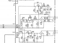
Power supply section, replaced D404 R401 ZD401 Z402 - all damaged from that lovely brown component glue.
Then I started working on the tuner issue.
Found the 'VT' voltage on the tuner and logic board are 0.01 volt, and the +30v rail from power supply to Logic board was 0.3v.
This was due to IC401 (2 amp fuse) on the power supply board being open.
I've now also replaced all related components - D402 D403 D405 D406 Q401
So entire 30v reg section in power supply is new, and working 100%
All Supply voltages as far as I can see are ok. Thats 5.6v 10v 13v 30v
Trying the previously mentioned trick off touching the crystal does result in a change to reception.
The only thing missing that I can see is this 'VT' voltage.
When in AM mode it is 29.6v - In FM mode it is 0.01 In either case it does not vary at all irrespective of tuning mode or frequency..
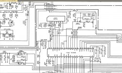
In the att pic, the VT line is pin 1 (right pin) of cn 1 (ylw).
I've also included relevant section of the power supply.
I have the hifi engine service manual so can post whatever sections are needed.
All help appreciated.
Customer has asked me to fix their SR4 which appears to be very similar to these TA4's etc.
This one had a low left channel output and non functioning tuner.
Missing channel was dry joints on the 'loudness' control board.
Tuner issue is same as this thread, am/fm seeks up down without stop, signal meter stays in one spot, and manual tuning reveals no stations.
I have done (as part of the normal service) full recap and resolder of all boards. Many dry joints fixed.
Power supply section, replaced D404 R401 ZD401 Z402 - all damaged from that lovely brown component glue.
Then I started working on the tuner issue.
Found the 'VT' voltage on the tuner and logic board are 0.01 volt, and the +30v rail from power supply to Logic board was 0.3v.
This was due to IC401 (2 amp fuse) on the power supply board being open.
I've now also replaced all related components - D402 D403 D405 D406 Q401
So entire 30v reg section in power supply is new, and working 100%
All Supply voltages as far as I can see are ok. Thats 5.6v 10v 13v 30v
Trying the previously mentioned trick off touching the crystal does result in a change to reception.
The only thing missing that I can see is this 'VT' voltage.
When in AM mode it is 29.6v - In FM mode it is 0.01 In either case it does not vary at all irrespective of tuning mode or frequency..
In the att pic, the VT line is pin 1 (right pin) of cn 1 (ylw).
I've also included relevant section of the power supply.
I have the hifi engine service manual so can post whatever sections are needed.
All help appreciated.
Attachments
I remember this thread from way back.
Have you tried resetting the uP by removing the backup battery or supercap ? Pins 34 and 35 of the uP will output a squarewave, the duty cycle of which will vary in relation to the tuning volts required. You need to scope that point and see if that is happening.
The two transistors turn that signal into an 'average' stable DC voltage (Vt).
If any buttons are stuck or leaky then that can inhibit the keyscan to the uP and make it appear functionally non-responsive.
Hey Mooly.
Yup, pulled battery (3v lithium) and then did your alfoil 'reset' procedure.
I only do this stuff as a 'hobby' so sadly I don't have a cro. Last one died.
Their cheap enough, maybe I should get a replacement.
All I have is a function generator (AF) and DMM (Fluke 179).
Yes I know, crippled for lack of tools.
Although the meter has frequency meter built in (100khz) I doubt that would show me anything of use.
Buttons don't appear stuck, display happily switches between functions, but leaky would be another issue.
Might check the signal going into the uP from the switches.
I found it strange I had VT on AM and nothing on FM, even if it was a solid voltage with no variation.
Both Vt values are valid values (0 and 30 volts), its just that they don't seem under uP control. If you use a DVM on the uP tuning line you should at least see it alter (quite drastically) as you try and tune, even if the readings are a bit meaningless in absolute terms.
You can usually gauge how the uP reacts to a damaged button. If you hold one in at random, do the others all work as expected or not ? If nothing works then its a pretty safe bet you haven't a damaged button. If it does all basically keep working then its possible a tuning related button could be a problem.
You have to cover all bases with faults like this.
I did think about checking pin 34/35 but had no idea what to look for.
Was thinking if either of the transistors are faulty they could be upsetting the uP.
Ta for the hints on checking button/uP function.
I'll do the 'hold one push others' with the other suggestions tomorrow and report my findings.
Many thanks for your help Mooly, and all the others that have posted in the past.
A little research here gives invaluable info..
Pins 34 and 35 will be a squarewave of around 5 volts amplitude but the duty cycle should be variable. A duty cycle of 50% (a perfect squarewave) would generate say 15 volts for Vt. If it were high for only 25% of the time then Vt would be 7.5 volts and so. The speed at which it runs is very high though, probably several kHz and so the meter will give a an indication of 'something' and something that should vary as you alter the tuning.
Ok so I couldn't wait and ran some tests...
Buttons.
If I hold in the am button, then push the fm button, it will switch to fm only while i push the fm button. All other buttons will operate that function (memories, tuning, mode)
If I hold in the fm button, then push the am button, nothing happens, it stays on fm. Again all other buttons will operate that function (memories, tuning, mode)
Pin 34/35.
on am, during search or manually tuning, 0.0vac and 0.013vdc
on fm, during search or manually tuning, 0.6vac and hovers between 4.9vdc - 4.79vdc
EDIT, thats across the full tuning bandwidth.
Trying to measure frequency gave no reading on any operation, possibly the voltage was below the meters sensitivity.
I should probably have mentioned... this is a USA version in Australia so am band is 10khz spacing vs 9khz spacing.
Side question, It's been a long time since I looked at cro's, are the lower models of tektronix lcd units worth considering these days ?
I also note I can get a tektronics lcd dso for about the same money.
I only need ~50meg dual channel.
Yes I'm aware of watching for "dual channel" vs "dual trace" sneaky buggers.......
Im open to suggestions.
Loved the kikisui (spelling) a previous boss had 25 years ago. But it was $$$$$$.
The voltages on pin 34/35 tie in with your measured tuning volts line. Both transistors would be off with 0 volts on the uP and that would generate a 30 volt Vt voltage as Q? (its not marked) would be off. The voltage you get on FM from the uP would at least turn both transistors on and that would pull the collector volts of Q? down toward 0v. So it sounds like they are at least working OK
The band spacing wouldn't stop it tuning, you just wouldn't be on the right frequencies for the broadcast stations on AM.
Its not easy faultfinding things like this. You do need a scope and you do need to go all around the uP looking for problem inputs before condemning it. I wouldn't like to say what scope to get tbh, I favour traditional analogue because a good 50 or 100MHz scope will show things that a digital one wont unless you are paying lots. I'm a bit out of touch with what the latest ones offer though and at what price.
Ok, so sounds like I reeeeeeally need a 'scope before I can proceed further with this beastie.
Guess it gives me the final push I needed to get one 😉
Scopes, yeah my last one was an ooooold bwd dual channel 50mhz crt one that finally died, um, 10 years ago.
Analogue vs digital, thanks for reminding me, yes I have heard analogue can show things digital can't.
I note, you can get analogue or digital with lcd displays, any idea how an analogue with lcd compares to a crt ?
Or is it just the front end processing I need to look at ?
You would have to give some examples of what you are looking at 🙂
True analogue on a CRO is what it says although it can have separate digital readouts and/or on screen info presented as well.
Digital scopes can be good but you pay for that. Rigol has a good name at the moment,
http://www.diyaudio.com/forums/equipment-tools/272121-oscilloscope-woes.html#post4292971
You need to check ALL pins have what you would expect to see... or at least something that seems reasonable. All data lines and key scans should be around 5 volts pk in amplitude. Remember the scope measures DC too and so you should check supplies and grounds are clean and at the expected values.
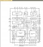
Check the prescaler outputs on IC601. Pin 5 looks as though it would be an input from the local osc in the tuner itself (probably to high a frequency, and to small in amplitude to see accurately on a scope) but there should be a clean lower frequency signal on pin 3 feeding the main uP. I would expect that to be 5 volt amplitude.
Check the prescaler outputs on IC601. Pin 5 looks as though it would be an input from the local osc in the tuner itself (probably to high a frequency, and to small in amplitude to see accurately on a scope) but there should be a clean lower frequency signal on pin 3 feeding the main uP. I would expect that to be 5 volt amplitude.
Alrighty.
Ta Mooly.
I did have a brief run today, probed all uP pins, few supply lines, one or two data lines, rest didn't do much or didn't make sense to me.
I shall have another play tonight.
I've forgotten so much about cro's.
And all these new buttons and menu driven systems take a long time to learn.
Well for me anyway.........
The 'scope has a neat feature where it can be 'unlocked' for extra things.
Changes it from a ds1054z into a ds1104z.
Although its sold as a 50mhz unit, mines now an unlocked 100mhz unit 😀
Finally.
Learnt a few tricks of this new crow 🙂
So, here we go..
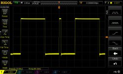
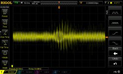
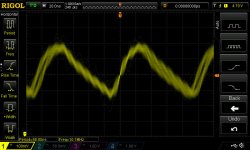
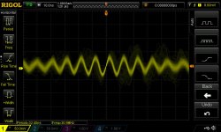
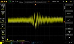
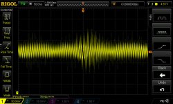
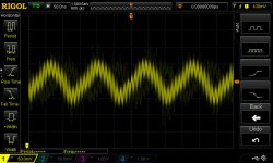
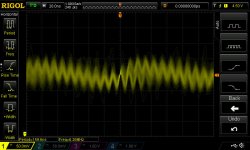
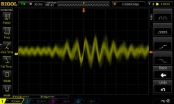
IC601
Pics in order of pins (pin 2 n/c and 4 gnd - neither measured)
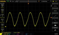
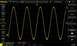
pin 1 / 3 / 5 / 6 / 7 FM / 7 AM
Learnt a few tricks of this new crow 🙂
So, here we go..
IC601
Pics in order of pins (pin 2 n/c and 4 gnd - neither measured)
pin 1 / 3 / 5 / 6 / 7 FM / 7 AM
Attachments
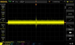


And for IC 602.
Most measured low level noise so didnt do 'shots' of those.
pins. 2 / 3 / 4FM / 4AM / 5FM / 5AM / 7AM / 7FM
Most measured low level noise so didnt do 'shots' of those.
pins. 2 / 3 / 4FM / 4AM / 5FM / 5AM / 7AM / 7FM
Attachments
-
 DS1Z_QuickPrint15.jpg70.5 KB · Views: 54
 -
 DS1Z_QuickPrint14.jpg70.8 KB · Views: 49
 -
 DS1Z_QuickPrint13.jpg76.2 KB · Views: 48
 -
 DS1Z_QuickPrint12.jpg77.4 KB · Views: 50
 -
 DS1Z_QuickPrint11.jpg74 KB · Views: 53
 -
 DS1Z_QuickPrint10.jpg70.3 KB · Views: 46
 -
 DS1Z_QuickPrint9.jpg72.1 KB · Views: 49
 -
 DS1Z_QuickPrint8.jpg77 KB · Views: 52
Other side of IC602.
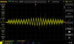
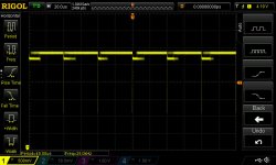
Pins. 22 / 34FM / 34AM / 34 FM SEEKING / 37
pin 23 is the same as pin 22
After all that, I think the ic is dead ? or am I wrong ?
Pins. 22 / 34FM / 34AM / 34 FM SEEKING / 37
pin 23 is the same as pin 22
After all that, I think the ic is dead ? or am I wrong ?
Attachments
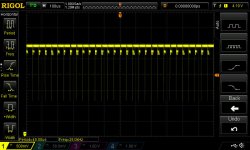
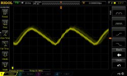
IC601 looks as OK in as far as its possible to tell. Pin 3 looks a bit odd but that is actually an input (from IC601). There's a nice clean squarewave on the output pin which is basic confirmation its OK. Pins 5 and 6 look spot on for the type of signal you would expect from the tuner.
IC601, pins 2 and 3 are normal (clock generator). Pins 4,5 and 7 look like noise... I think these should be static logic levels that will only have data present when you are pressing keys to change the band switching and so on.
Pin 34 doesn't look correct. Its not normal to see a small amplitude logic signal riding just below the high logic level... is the IC faulty possibly with a problem on that output port drive stage... I've been here many times and its never (99% never) 'the big chip' but this is maybe pointing that way.
It is worth you unsoldering R602 and measuring pin 34 again to see if the level has changed.
- Status
- Not open for further replies.
- Home
- Source & Line
- Analog Line Level
- Nakamichi TA4A tuner has no output