Some progress
Some progress, sort of...
I did the foil trick again from the top of the board, and removed and re-set all the flat cables, with the exception of one that was hot-glued in place due to the locking cap being broken. Also re-connected the battery.
The tuning numbers are now there again, and can be adjusted up and down. However, there's still no sound under Tuner. I think I will remove and re-set the cable that's glued into place, just for completeness.
I also followed advice from AK, and tried to reset the tuner voltage at TP01 and L305, but it does not seem to have an effect.
So - it seems now to be back where I started, but not such a bad place to be.
Is there a "next" to do here?
Thanks again.
That sounds more promising...
Don't know what test gear you have but I would check the supplies to the front end module, page 32 of pdf marked 7.2.1 tuner section. Check B+ supply is correct and also that the varicap tuning voltage sweeps from 0 to ???? 18 or so volts as you tune up the FM band. That's pin 5 on the module.
If that's OK then it's a case of working through 🙂
Well, didn't exactly know what to check per your instructions, but I did find out that the 13V that should be at connector 15 is only 3.66 volts. Is that indicative of a bad cap?
Where else would I look?
Where else would I look?
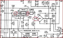
Page 35 of pdf, check U953 a circuit protector (fuse) value is 40 times the marking so an N10 is 400 milliamp anti surge. It feed 7812 regulator. Trace the rail from there if that happens to be OK.
Edit, an N15 is 600ma
Edit, an N15 is 600ma
Thanks. Will get to it this afternoon sometime. Looks like it's behind the faceplate at the controller panel.
Right, it's on the controller board, not the main control panel. Not sure where to check voltages, since the U953 is directly on the PCB, but the jumper right next to it reads 5.43 volts.
Key points to check,
Thanks for the notes. I measured 23.4 at the leftmost point (the pin one of cable cn-41), but haven't figured out yet how to access the next two points (or exactly where they are). Any suggestions would be appreciated by this newb.
It's been a hectic weekend, and I may not get back to it until mid-week to research it further, but wanted to keep this alive.
You just have to be logical and follow it through. 23 volts sound OK (fuse/cp must be OK) so measure on the pins of that 7812 regulator or across that cap C963. If you have 23 volts in and low voltage coming out of the reg then it's probably (barring a short on the output) faulty. Is it hot ?
The voltage you quoted a few post back as being 3.66volts is that rail from the regulator. So you have to locate that reg and just trace from there. Could well be the reg though, it's a typical failure mode.
The voltage you quoted a few post back as being 3.66volts is that rail from the regulator. So you have to locate that reg and just trace from there. Could well be the reg though, it's a typical failure mode.
Hello again - Been awhile, hope you're still interested in this. I couldn't quite measure the voltages across the caps because the new caps are a bit larger. Some I bought locally and some were ordered, and some came out a bit larger than the originals (some I ordered one voltage step up).
So I thought I would measure a few places for voltage and report back.
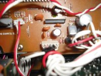
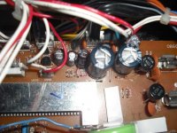
It seems to me that the tuner board may not be getting enough voltage. The connector CN38 has just a few millivolts: Left to right: 9.6; .2; .5; .5; .3 This appears to have the largest insulation on the brown/white wires so I thought it might be power into the tuner board.
The three connectors at the top left of the tuner board show anywhere from 0 to 5 volts at some of the wires. I can diagram them all out if that would be a help.
As you can see I'm a little stuck on this at the moment. Any suggestions would be appreciated. I wouldn't be surprised if it was a small thing I missed somewhere. Could there be a bad tantalum cap?
So I thought I would measure a few places for voltage and report back.
It seems to me that the tuner board may not be getting enough voltage. The connector CN38 has just a few millivolts: Left to right: 9.6; .2; .5; .5; .3 This appears to have the largest insulation on the brown/white wires so I thought it might be power into the tuner board.
The three connectors at the top left of the tuner board show anywhere from 0 to 5 volts at some of the wires. I can diagram them all out if that would be a help.
As you can see I'm a little stuck on this at the moment. Any suggestions would be appreciated. I wouldn't be surprised if it was a small thing I missed somewhere. Could there be a bad tantalum cap?
Attachments
Well, didn't exactly know what to check per your instructions, but I did find out that the 13V that should be at connector 15 is only 3.66 volts. Is that indicative of a bad cap?
Where else would I look?
Page 35 of pdf. Connector CN31 has the 12 volts from the reg on pin 4 of the connector.
That goes to CN 31 on page 33. From there it feeds off to other areas as well.
You are going to have to trace these yourself with the unit in front of you and measure along the way.
Find the point on the tuner where the supply is missing.
Pin 11 of U302 (ic on page 33). Is there 12volts there ?
Also check the line from CN31 pin 5 on page 33 marked "FM". Does the voltage go to around 12 volts on FM ? Does that voltage arrive at pin 5 of U301 ?
Page 35 of pdf. Connector CN31 has the 12 volts from the reg on pin 4 of the connector.
That goes to CN 31 on page 33. From there it feeds off to other areas as well.
VOLTAGE AT PIN 4: 0.32V
You are going to have to trace these yourself with the unit in front of you and measure along the way.
Find the point on the tuner where the supply is missing.
Pin 11 of U302 (ic on page 33). Is there 12volts there ?
VOLTAGE AT PIN 11: 0.31V
Also check the line from CN31 pin 5 on page 33 marked "FM". Does the voltage go to around 12 volts on FM ?
VOLTAGE AT PIN 5: 0.00V
Does that voltage arrive at pin 5 of U301 ?
Mooly,
Many thanks for your kind patience and suggestions. I'm not well versed at troubleshooting or reading a schematic (as you know by now). I did find the corresponding points on the board diagrams and tested there for U302, etc.
Does this mean the issue is in the voltage supply to the controller board from the main board? If so, how to access?
You really need to post the voltages you are measuring at all the above points I mentioned.
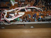
I can't tell you how to access the various point, I would need it in front of me but from your photos it all looks fairly straightforward to measure on. Was there 12 volts on U302 (an integrated circuit) on pin11 of that IC?
We are struggling a bit I think...
I can't tell you how to access the various point, I would need it in front of me but from your photos it all looks fairly straightforward to measure on. Was there 12 volts on U302 (an integrated circuit) on pin11 of that IC?
We are struggling a bit I think...
I did post the voltages in capitol letters as part of the quoting of your previous post. Maybe you skipped past it? Is this what you were looking for? If not, please let me know what else would work.
Sorry... my fault, just saw it as a quote... it's bit early here lol.
Let me have a look, I'll come back to you in a little while.
Let me have a look, I'll come back to you in a little while.
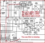
You have a missing 12 volt rail. Pin 4 of CN 31 is missing the feed from the regulator.
On this diagram that point, pin 4, goes direct to the output of the reg.
Are you sure the "fuse" is OK that feeds it. If so and you have 20 or so volts entering the reg and nothing coming out then it's faulty.
On this diagram that point, pin 4, goes direct to the output of the reg.
Are you sure the "fuse" is OK that feeds it. If so and you have 20 or so volts entering the reg and nothing coming out then it's faulty.
Attachments
Does that make sense ? 🙂
I'm still locating it on the board diagram. Is U951or U953 the regulator?
(BTW, it's near midnight here, so my eyes are a bit tired to read the fine print).
BTW, thanks for such a quick response!
- Status
- Not open for further replies.
- Home
- Source & Line
- Analog Line Level
- Nakamichi TA4A tuner has no output