At 100W bulb rating, you can expect it to glow dimly due to the receiver or amplifier's total idle current. If the bulb glows brightly when you touch part of the circuit with a meter probe, it is oscillating with the meter's impedance added to the circuit that way or perhaps due to RF energy received and detected like a radio. You can verify which it is by touching with just a disconnected probe lead or perhaps both probes in series.
It seems crazy but audio circuits can and often do perform more than one function simultaneously. Typically, our focused analysis methods will ignore abnormal modes and filter out undesired responses while in reality, the amplifier or receiver may be behaving badly.
As mjona pointed out, analysis is invalid with the dynamic resistance of the bulb in the power supply but it's there primarily for safely powering while there may be unknown or unproven faults, not for use with loads yet. For an essential tool, it's also unusually cheap and simple to DIY so there's not a lot to criticise, apart perhaps from stability issues like this one may prove to be.
Last edited:
I used a 100W bulb. It normally glows very very dim when the amplifier is connected to it, regardless of whether playing music or just idling. But I just couldn't understand why it lit brightly when I touched one end of that resistor with the multimeter probe and I feared some component(s) would burn if I was to repeat the reading while connected to the mains, without any type of current limiter.
I hope you are now reassured by Ian Finch's explanation and are confident enough to take the measurements with the power on. If you are in doubt there are a couple of tips that you might think about.
First strip out the wire from the insulation of a small enough length to make a sleeve you can slide the metal of the red probe into leaving just the tip uncovered.
In that way you minimize the risk of touching two leads of a transistor at the same time causing a short.
If it is really difficult to reach the legs of those with heat sinks a pair of parrot clip test leads would be a good addition to your tool box.
With such clipped in place and with the black probe in the black speaker out terminal you have two hands free to work with.
Step one would be to turn the amplifier on keeping a digit on the button moisten one on the other hand to detect sources of rising heat.
It is already known that Q407 and Q408 are running hot. Temperature is a factor in current gain and these transistors seem to be passing more than enough.
Re Q405 and Q407 I sought the voltage drop across R437 which will show their combined current.
How much is drawn by Q405 requires measuring the voltage drop across R435. From this the separate currents in Q405 and Q407 can be assessed.
I am particularly interested in the current for Q405 because it is part of the Vas. Do these measurements by the method I described earlier now this has been simplified.
Repeat the same process for the matching equivalent components in the other channel
Last edited:
Here are the measurements:
R437 0.74V (10.88mA)
R438 0.74V (10.88mA)
R435 0.59V (1.53mA)
R436 0.60V (1.53mA)
Looking forward to your conclusions 🙂
R437 0.74V (10.88mA)
R438 0.74V (10.88mA)
R435 0.59V (1.53mA)
R436 0.60V (1.53mA)
Looking forward to your conclusions 🙂
1.5 m.A. of collector current is too low for Q405 and Q406 for the amplifier to be working properly.
The BC556Bs were not replaced after the amplifier failed so we need to look at the Vbe which should be about 0.55V for each.
The BC556Bs were not replaced after the amplifier failed so we need to look at the Vbe which should be about 0.55V for each.
Last edited:
I might have done a stupid thing... I tried to measure Vbe in-circuit for Q406. While probing between B and E, I noticed that the transformer started to buzz, but the amp was up on one side (so I could probe that back of the PCB). It took me some seconds until I scaled up the DMM for a reading. It showed some 34V. I quickly turned it off and when laid the amp back on the table I noticed the main heatsink was very hot (barely could keep my hand on it), as well as the outputs on that channel and the emitter resistors. I plugged it in the DBT and everything looked normal. DC offset measurement doesn't show much of a difference (about 0.3mV on each channel) so I assume I didn't fry the outputs again.
The only thing I did different from measuring the resistors earlier was that I probed the transistor while the amp was on as I couldn't clip the leads on the top side of the PCB so I used pointed probes from underneath. I expect the behavior was similar to what I saw the last time I tried to measure those resistors while the amp was on.
Should have I pulled the transistors and measure them off circuit? (my multi component tester also measures transistor Vbe AFAIK)
Last edited:
The collector current of Q405 Q406 includes both the current across R435 R436 and the current into the base of Q407 Q408. R435 R436 establish the gain of Q407 q408 along with the collector resistors R437 R438.1.5 m.A. of collector current is too low for Q405 and Q406 for the amplifier to be working properly.
The BC556Bs were not replaced after the amplifier failed so we need to look at the Vbe which should be about 0.55V for each.
The readings on your transistor tester are consistent with what might be expected from Q406 in circuit however these have their own supply and inject current into the transistor under test. These are not designed for testing with circuits under power with the setting you have there.
The collector current of Q405 Q406 includes both the current across R435 R436 and the current into the base of Q407 Q408. R435 R436 establish the gain of Q407 q408 along with the collector resistors R437 R438.
I am aware of that but the measurement should be close enough for analysis purposes.
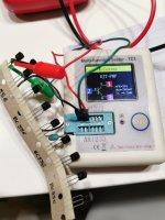
this is the tester (cheap chinese little thing but seems to work nicely)
It says Multi-Function Tester on the case. It has what look like USB ports and leads with clips at the ends. Check the instructions to see if other ports can be used to test voltage and if there is a hold function to display the measurement.
If so the leads have clips that should allow you to secure the red probe around the base or emitter lead put the other in the black output terminal connecting to earth.
This will allow you to work from the top of the pcb and put the meter where it is the centre of focus.
With two hands free you can turn the power switch on or off quickly with one and start the meter with the other.
I think the base current for Q407 and Q408 will be less than normal because of the low current levels in Q405 and Q406, and heating of Q407 and Q408 has increased their current gain in greater proportion to their base currents.
They are indeed nice little testers with a nice, crisp display and rechargeable via USB too. The TC1 model is an updated one but still based on similar ATMEGA 328 microcontrollers and firmware to other versions that have been around for many years now. Long description, model comparisons and review here: The evolution of the Electronic Component Tester (Multi-function Tester TC1 review) - YouTubethis is the tester (cheap chinese little thing but seems to work nicely)
There's no hold function that the reviewer mentions or I'm aware of but it was only about US $20 delivered with accessories.
As mjona may be warning, I would not trust the results of testing any components or semis in-circuit, though. The most obvious problem there is that the test voltages generated by the tester will be at low power and relatively high impedance, thus easily loaded by the amplifier circuit resistances such that the results will likely be false/meaningless.
Last edited:
I think there's been some confusion regarding last night's episode...
I'll explain what happened:
not knowing whether I should measure the transistors in circuit or pulled out I assumed I had to measure them in circuit so I tried to measure Vbe by touching the base with one probe of the digital multimeter (not the tester) and the emitter with the other probe. That's when the transformer started to buzz (and the current started to rise I assume). The DMM was set to the 200mV DC division and the reading was 1 (as in out of range). It took me some seconds until I realized it was out of range, not 1mV and set the DMM to the next division. Still 1 so went up a notch to the 20V division. Only then I had a reading of 34ish VDC and realized something was wrong, shut the amp down and noticed the heatsink, emitter resistors and outputs were hot.
then, after posting here and getting the first reply I decided to test an unused BC556 with the multi function tester because I wasn't totally sure it also measured Vbe, and that's what was in the photo. So I never used the multi function tester on the actual amplifier circuit.
I'm a bit confused whether I was measuring the right stuff or not. I assumed measuring Vbe meant placing one probe on the base and the other on the emitter while the amp was running, but after your replies I'm now thinking that I should have measured voltage drops between base and ground, and emitter to ground respectively, and then substract one value from the other to get the Vbe. As it seems, I'm not really knowing my way around transistors yet...
You are on the right track now in measuring separately between base and ground and emitter and ground as you call it or earth as I did, and doing the mental arithmetic. The circuit diagram shows various points connected to the earth symbol. It is easier to work with only one hand in the chassis and keep one free for other tasks which is the reason for my suggesting putting the black probe into the black speaker output terminal - either one will do.
Modern multi-meters have high input impedance for measuring voltage so you should not have a repeat of last nights performance if you do the tests as per this discussion.
All the same keep one hand on the on-off switch as a standby precaution.
Modern multi-meters have high input impedance for measuring voltage so you should not have a repeat of last nights performance if you do the tests as per this discussion.
All the same keep one hand on the on-off switch as a standby precaution.
I replaced Q405 and took another measurement:
NEW Q405 (BC556) static: hFE=392, Vbe=698mV, Ic=6.2mA
in-circuit: Vb = 38.3V, Ve = 39V
OLD Q405 static: hFE=331, Vbe=691mV, Ic=6.2mA
-----------------------------
OLD Q406 static: hFE=331, Vbe=691mV, Ic=6.2mA
in-circuit: Vb = 38.4V, Ve = 39V
NEW Q406 static: hFE=392, Vbe=690mV, Ic=6.2mA
so, in-circuit measurements for Vb and Ve were made with the new transistor in place for the left channel and with the old one for the right.
maybe I did a mistake when measuring voltage drop across R435 and R436...
Base of Q407 is one of the high gain points in the amp. Only exceeded by base of Q405. Attaching a radio antenna there is likely to pick up a lot of radio emissions. Such antenna being a meter lead. And you are probably wearing a radio in your pocket, a cell phone. So oscillation occured.maybe I did a mistake when measuring voltage drop across R435 and R436...
Such measurements could be made more safely with a coil clipped to the end of the meter lead. Use a lead of the coil to probe for the DC measurement. Such coils can be salvaged from switcher power supplies, flat screen TV, or tuner of CRT TV. Coil would block the RF in the meter lead from bleeding into the VAS base.
I put coils series the temperature pickup diodes of my AX6, going back to the driver bases: Since my temp pickup & output transistors are 6" away from the drivers by flexible wires floating through space. Audio amps don't need to amplify RF frequencies; we can't hear them and the musicians aren't making them.
I replaced Q405 and took another measurement:
NEW Q405 (BC556) static: hFE=392, Vbe=698mV, Ic=6.2mA
in-circuit: Vb = 38.3V, Ve = 39V
OLD Q405 static: hFE=331, Vbe=691mV, Ic=6.2mA
-----------------------------
OLD Q406 static: hFE=331, Vbe=691mV, Ic=6.2mA
in-circuit: Vb = 38.4V, Ve = 39V
NEW Q406 static: hFE=392, Vbe=690mV, Ic=6.2mA
so, in-circuit measurements for Vb and Ve were made with the new transistor in place for the left channel and with the old one for the right.
maybe I did a mistake when measuring voltage drop across R435 and R436...
Those figures are consistent with what I expected under normal conditions
The equation for the gain of these transistors is Av=gm.RL where RL (the collector load) is in k Ohms and gm is approximately 40 times per m.A. of collector current.
In post 143 you worked out from the voltage drops across R435 and R436 that the emitter current in these transistors is of the order of 1.5 m.A. since gm is defined as Ic/Vbe 1.5 m.A. over 680 m.V. of Vbe does not compute.
I have something on this afternoon so I will have to come back to this later. If there is something you want to do in the meantime try reducing the output transistor emitter resistor values and see what effect this has on Vbe and resistor voltage drops.
By chance did you set up the output transistor current by the method in the service manual with the One Ohm test resistor in series with Q415 and Q416
- or did you do that with those resistors shorted. If you fit emitter resistors in series with Q415 and Q416 emitters, for an accurate assessment of standing current you need to bridge the test resistor and measure the voltage at either end of the added emitter resistors.
I'm assuming the test resistor is short circuited at present in which case you could take the measurement separately with one probe with the other in the black output terminal.
In that case you can measure from each red output terminal to the end of the wires which connect to the transistor Q415/Q416 emitters. These may be accessible on the pcb you fashioned.
Yes, I used the method in the service manual. I'll check and see what comes up from your description. I didn't think it through apparently. 🙂
LE:
Anyway, shouldn't I measure voltage drop across Q415/Q416's emitter resistor to calculate idle current? If I measure voltage drop between Q415's emitter (common point between the transistor's emitter and the emitter resistor) and the red output terminal (or any other reference point) how will I calculate the current, not knowing the resistance (since I'm not measuring across a resistor)? And why am I using the red output as a reference?
Sorry for the silly questions... I'm just trying to understand the concept rather than just poking things with the probes and hoping no smoke comes out.
I'm not sure what to make of this...I'm assuming the test resistor is short circuited at present in which case you could take the measurement separately with one probe with the other in the black output terminal.
Anyway, shouldn't I measure voltage drop across Q415/Q416's emitter resistor to calculate idle current? If I measure voltage drop between Q415's emitter (common point between the transistor's emitter and the emitter resistor) and the red output terminal (or any other reference point) how will I calculate the current, not knowing the resistance (since I'm not measuring across a resistor)? And why am I using the red output as a reference?
Sorry for the silly questions... I'm just trying to understand the concept rather than just poking things with the probes and hoping no smoke comes out.
- Home
- Amplifiers
- Solid State
- NAD 7020i sudden death