Some people really like the warm, sweet sound of many high-end amplifiers but these are too expensive for most of us, even in pre-loved condition so when we find a similar sound quality in a cheap product, of course it becomes popular and earns a good reputation among audio enthusiasts - rich and poor. That's what the NAD 3020/7020 series proved to be.
As you may be saying, the hype isn't supported by the build quality and perhaps the sound you hear isn't the best but you may also need to get your support equipment, speakers, source etc. set up differently first. Give this some time, thought and listen to a wide range of music types over a wide range of volume settings etc. before you decide against a new amplifier or system, with and without the help of your A/B box.
Systems of several components tend to "grow on you" and reverting to your old system can be equally disappointing after some days have passed. Funny, that
Change "can be" to "will be" disappointing in the last paragraph and you are probably right.
I would ask you to consider the level of negative feedback across a 0.61 Ohm emitter resistor and the fact that transistors need a Vbe of 0.6 to work in their linear region.
For Vbe values below 0.6V the gm plot is curved and non-linear - a no go area.
It is important to see where changing the voltage on a transistor emitter and the consequent changing of Vbe for the particular device is going.
Are you referring to the emitter resistors I added? They are 0.56ohm but I could swap them for 0.33 if the value used is to high.
Since about 1964 class AB transistor amps have handled the "crossover distortion" of the <.7v Vbe of silicon output transistors, by leaving both transistors turned on at all times. This is reflected by the idle bias current, managed by transistor Q409 410. Adequate idle bias current should keep both output transistors out of the shut off part of the gm curve at all times. ???? Zenzaman has said he is getting specified OT idle bias current after emitter resistor installation, even without modifying the circuit around Q409 410.I would ask you to consider the level of negative feedback across a 0.61 Ohm emitter resistor and the fact that transistors need a Vbe of 0.6 to work in their linear region.
For Vbe values below 0.6V the gm plot is curved and non-linear - a no go area.
.
Higher value emitter resistors cut the maximum power available. I suspect the power transformer of a NAD7020i limits the output power available so effectively that .56 ohm emitter resistors versus .33 ohm emitter resistors will be inaudible. Ie the rail voltage probably sags pretty well near the power limit. What was the power limit, 20 w/ch?
As far as the "sweetness" of NAD amps, I find major sonic differences in speakers, not amps. As my income went up I've had 4 generations of better & better speakers, as measured by accuracy of sound on piano source. I own & play an excellent piano, to serve as calibration source vs cheap speakers. The better speakers (Peavey 1210, Peavey SP2-XT) would reveal the fuzziness of my 1% HD ST70 tube amp, versus the accuracy of ST120 (after djoffe crossover distortion mod), and later. .1% HD and lower amps don't affect sound much, IMHO. <.1% Amps have much less coloration than a bargain speaker. I just bought a .1% HD amp (M-2600), and will have to replace my charity resale shop speakers with something much better to hear the difference between it and the .03% HD CS800s I bought 2 days later.
Last edited:
Are you referring to the emitter resistors I added? They are 0.56ohm but I could swap them for 0.33 if the value used is to high.
I don't see that as being of much help. Q403 and Q401 have separate but dissimilar bias arrangements. Between that involving Q403 there are five emitter diodes up to Q415 emitter resistor.
For Q401 up to Q417 emitter resistor you have only two. So far there have been no offers to change the bias arrangement for Q403 and that includes me.
Last edited:
There is also a further complicating factor in that Q401 emitter has a direct route to the output via R430 // R432 where an additional emitter resistor has been interposed at the end of the chain.
Some mods to the bias of Q401 might fix this but getting two bias adjustments to work in harmony is another issue but count me out on that one.
Some mods to the bias of Q401 might fix this but getting two bias adjustments to work in harmony is another issue but count me out on that one.
Since about 1964 class AB transistor amps have handled the "crossover distortion" of the <.7v Vbe of silicon output transistors, by leaving both transistors turned on at all times. This is reflected by the idle bias current, managed by transistor Q409 410. Adequate idle bias current should keep both output transistors out of the shut off part of the gm curve at all times. ???? Zenzaman has said he is getting specified OT idle bias current after emitter resistor installation, even without modifying the circuit around Q409 410.
So are you saying that there is no crossover distortion with and without emitter resistors. If you are we are in agreement. Cross coupling the emitters of the drivers with a resistor means these remain in conduction through the notional zero crossover point.
The feedback goes from the output, relay connection to C433 & the coil, to the emitter of Q401. this is just like 2nd generation amps like Armstrong 621 & Apex AX6. No long tailed pair. Q403 has the music input but through 62 kohm instead of 3.3 k like Q401. The resistance to upper rail is lower to base of Q403 than to the music. So I think Q403 has some sort of DC bias function to the VAS Q405. Q403 is not there to amp the music. No feedback to Q403 either. Q401 is the music input voltage amplifier.
So zenzaman, I think you should do a lot of listening to the NAD7020i before you do any further modification. Might be nothing wrong. I use piano CD's including top & bottom octave solo. Versus a real piano. Beethoven Appasionata, + top octave solo of Peter Nero Young & Warm & Wonderful. When I fall in love track. Very tough for amp & speaker to get those right.
Or if you have good software in your PC, a HD and IM test at 1 w and max power, into an 8 ohm >70W resistor.
Last edited:
This isn't a new, unexplored problem or solutions. The matter has been discussed here several times in the past and recently added to by PRR, #59.Change "can be" to "will be" disappointing in the last paragraph and you are probably right.
I would ask you to consider the level of negative feedback across a 0.61 Ohm emitter resistor and the fact that transistors need a Vbe of 0.6 to work in their linear region.
For Vbe values below 0.6V the gm plot is curved and non-linear - a no go area.
It is important to see where changing the voltage on a transistor emitter and the consequent changing of Vbe for the particular device is going.
So an essential electrical difference here between epi- and hometaxial transistors is an intrinsic emitter resistance in the NPN-only hometaxial process but virtually none with the cheaper epitaxial process.RCA 1966 (hometaxial) 2N3055 was rated 115W........This part shows ~~1.3Vbe at 5 Amps Ic, so "acts like" 0.14 ohms internal emitter resistor due to significant parasitics.
To approximate the level of feedback associated with this resistance, an external resistance should be added in the emitter circuit and to be consistent, perhaps we should only add it to the 2N3055 emitter. As it turns out though, there have been no further problems with fitting standard values of 0.22 -0.33R to both output transistors, on the premise that they are both now epitaxial and symmetry in more-or-less standard push-pull output stages isn't a bad thing.
Anyway, the values of OR61 or 0R56 are not mine nor anyone else's suggestion. Nor are these indicated values, just convenient ones from the OP's stock of parts, I imagine. It will likely cause problems as you say but not considered in my argument or comments.
Last edited:
Re
In post 90 I asked zenzaman to measure the voltage drop across R437 and R438. He did not reply and I had penned a follow up request but I lost it scrolling through other thread pages. His mind was on output stage Iq which was not relevant to the question I asked. On reflection the voltage drops across R435 and R436 should also be measured to determine the level current in Q405 and Q406.
If Q407 and Q408 are running more current than necessary that will reduce the voltage at the emitters of the latter transistors and reduce the current through these. When transistors are running hot so that will increase their current gain and accentuate the current reduction in Q405 and Q406 and since these are the dynamic elements in the Vas that result would reduce the loop gain of the amplifier which has implications for stability.
Post # 89 # 90 are IMHO about the hot Q407. I think the 16 ma quoted in those posts talks about the currrent in Q407.
28 mv across 1 ohm of R455 should be fine, with emitter resistors. 20 ma is nominal in my quasi comp amp which mjona seems to feel has absolutely nothing to do with fully comp amps. I think that opinion is a little strange. Turn down to 20 ma if you are worried.
Personally I'd put a heat sink on Q407 the VAS. Lots of amps that need repair in the forum have blown a VAS transistor.
In post 90 I asked zenzaman to measure the voltage drop across R437 and R438. He did not reply and I had penned a follow up request but I lost it scrolling through other thread pages. His mind was on output stage Iq which was not relevant to the question I asked. On reflection the voltage drops across R435 and R436 should also be measured to determine the level current in Q405 and Q406.
If Q407 and Q408 are running more current than necessary that will reduce the voltage at the emitters of the latter transistors and reduce the current through these. When transistors are running hot so that will increase their current gain and accentuate the current reduction in Q405 and Q406 and since these are the dynamic elements in the Vas that result would reduce the loop gain of the amplifier which has implications for stability.
Last edited:
I would use lower, as in 0.15 - 0.22 ohm emitter resistors myself, but if it's all you have, O.33 is at least better than 0.56 ohm. BTW, did you ever try powering and listening to music through the amplifier after fitting the resistors?Are you referring to the emitter resistors I added? They are 0.56ohm but I could swap them for 0.33 if the value used is to high.
In post 90 I asked zenzaman to measure the voltage drop across R437 and R438. He did not reply
I probably missed that. Anyway, the amount of information you guys delivered is quite overwhelming for a beginner 🙂
Initially I ordered some 0.33ohm resistors but for some reason I wasn't very sure of their quality. Then, after reading some of indianajo's posts (if I recall correctly) about the emitter resistors used in his pro amps I tried to find some 0.5ohm resistors and the closest match were 0.56. Then, after more replies I went and bought another batch of 0.47 I believe (I'll have to check today to be certain). If needed I'll go and see if any lower values are available.
Also, I'll reread the last couple of pages and take the measurements you wrote about.
I did listen to it for a couple of hours but connected to my 'test' set of speakers (a pair of Dynaco A10 that I won't cry too much over in case things go south). I couldn't say if it sounded the same, worse or better than before the work I'd done on it because my acoustic memory is extremely short (that's why I bothered with the a/b box). Next week I'll receive two dozen banana jacks so I can make enough cables to be able to compare amplifiers and then I'll see how it stacks against a NAD 3240PE and the Kenwood KA3700 that I worked on before the NAD.
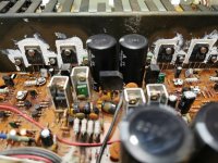
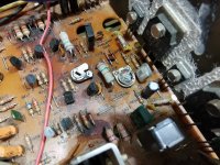
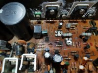
I opened the 3240 up last night just to see what's inside and... it's been worked on, that's for sure. I'm inclined to believe it might not be the tidiest work. Outputs are of different makes, electrolytics were only partly replaced (the 7020 had all electrolytics of the same brand, the 3240 has at least 3 different brands), a trim pot looks different from the rest and parts of the PCB are quite discolored but I'm not sure if it's just glue residue or burn marks. On the other side it sounds good to my ears and never really let me down for the last 2 years since I bought it. Not sure whether messing with it is a good or bad idea 🙂
Attachments
Last edited:
I would guess that someone has repaired that, got it sort of working, then sold it on quickly before it fails again! (Sorry.)
The big issue with these 3240 and similar PE models is that they are not simple amplifiers. It takes more than one look at the schematic to realise that the power supply rail voltages vary continuously, according to the demands of the amplified signal level. This is often referred to as a class H design which should mean modulated power rails, while class G refers to simpler, switched rails but as usual with supposedly international conventions, half the planet winds up believing the opposite is true because their education didn't have it right either.
If in any doubt about what you are are tackling, get professional help from a pro. audio technician to repair these - it's too easy to get lost if you don't understand how they should work.
There is an interesting and informative thread by suzyj here, about the common 3240PE problems she resolved and I found it quite helpful. DIY includes repair? NAD 3240PE advice needed...
I opened the 3240 up last night just to see what's inside and... it's been worked on, that's for sure. I'm inclined to believe it might not be the tidiest work. Outputs are of different makes, electrolytics were only partly replaced (the 7020 had all electrolytics of the same brand, the 3240 has at least 3 different brands), a trim pot looks different from the rest and parts of the PCB are quite discolored but I'm not sure if it's just glue residue or burn marks. On the other side it sounds good to my ears and never really let me down for the last 2 years since I bought it. Not sure whether messing with it is a good or bad idea 🙂
I would not mess with it, some trades people I know won't fix gear that has been thrashed to the point of failure and previous repair work looks dodgy.
When you do your amplifier comparisons, indianajo mentioned music with piano. It is more difficult to make comparisons of electronic music or vocals that have been enhanced by that means.
In post 90 I asked zenzaman to measure the voltage drop across R437 and R438. He did not reply and I had penned a follow up request but I lost it scrolling through other thread pages. His mind was on output stage Iq which was not relevant to the question I asked. On reflection the voltage drops across R435 and R436 should also be measured to determine the level current in Q405 and Q406.
I just checked backwards and it seems I actually did measure that voltage drop, but got no explanation for the values or behavior and my reply probably got lost in the following ones.
ok... so I measured the voltage drop across R437 and R438. Using a DBT I get .78V that translates into a current of 11mA on both channels (inputs shorted, volume to zero, tone adjustments off, impendence selector set to 8ohm). I didn't measure when plugged directly into the mains because when touching one probe to the left leg of the resistor first the bulb lit up and stayed lit until I shut the amp off and restart. It seemed a repetitive behavior and only touching the right leg first and then the left got me a reading and no light intensity increase on the bulb (since I don't know what to make of this other than some current surge I preferred to not have any magic smoke come out of the amplifier).
I checked my resistors and they are 0.39ohms. I'll see if I can find even lower values locally.I would use lower, as in 0.15 - 0.22 ohm emitter resistors myself, but if it's all you have, O.33 is at least better than 0.56 ohm. BTW, did you ever try powering and listening to music through the amplifier after fitting the resistors?
Thank you for the link 🙂
The readings on the circuit diagram are under power with no signal input and no load.
With a light bulb in series with the mains the voltage readings are invalid. My understanding of the light bulb test is that this should not illuminate and whether or not it does depends on the wattage of the bulb. We need to know if we are seeing a false alarm or not.
With a light bulb in series with the mains the voltage readings are invalid. My understanding of the light bulb test is that this should not illuminate and whether or not it does depends on the wattage of the bulb. We need to know if we are seeing a false alarm or not.
Last edited:
I used a 100W bulb. It normally glows very very dim when the amplifier is connected to it, regardless of whether playing music or just idling. But I just couldn't understand why it lit brightly when I touched one end of that resistor with the multimeter probe and I feared some component(s) would burn if I was to repeat the reading while connected to the mains, without any type of current limiter.
- Home
- Amplifiers
- Solid State
- NAD 7020i sudden death