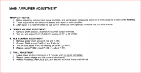
I'm also mystified by a particular need to change the setting method if you have added only small value emitter resistors. The emitter resistor of the epitaxial 2N3055 could be be ignored anyway, if its value is similar to the intrinsic DC resistance of the original transistor type. If they are much higher resistance values, it may well be a different matter.
We set DC bias current first in ambient conditions, then repeat, allowing only 5 minutes to warm up without the cover in place so this isn't going to be a precise setting in all climates, anyway. That's not to say that the settings weren't carefully considered to result in reasonably correct and reliable operation almost anywhere, though.
We set DC bias current first in ambient conditions, then repeat, allowing only 5 minutes to warm up without the cover in place so this isn't going to be a precise setting in all climates, anyway. That's not to say that the settings weren't carefully considered to result in reasonably correct and reliable operation almost anywhere, though.
LE:
I'm not sure what to make of this...
Anyway, shouldn't I measure voltage drop across Q415/Q416's emitter resistor to calculate idle current? out.
Yes but try to do that from safe access points. If you did the set up test with the test resistor in circuit that was the correct method without the emitter resistors added but this invalidates the measurement.
The standing current is adjustable but it has not been measured the way it should be. The red output terminal is connected to the end of the emitters.
You have had one incident of instability when taking measurements. There is a coil between the emitters and the red output terminal.
It will have nowhere near the resistance of the test resistor and the red output terminal is accessible from the outside of the case.
The measurements you gave me for Q405 and Q406 collector current of 1.5 m.A. are too low for the amplifier to be working properly even though the Vbe levels are correct.
A typical collector current for these transistors in another amplifier would be 6 m.A. and with 1.5 m.A. that would make the whole unstable. The reason for that is the loop gain will reduce in line with the equation I gave you, phase would start to change at a lower frequency and the compensation becomes inadequate.
The NAD is not a standard design the Vas is part of a complementary feedback pair so if the emitter voltage of either transistor e.g. Q405 and Q407 a change in one will be compensated for by a change in the other. As a cell this is hanging together but Q407 is running hot but the cell is not a case of thermal runaway.
If this was a Darlington arrangement with 1.5 m.A. collector current for the equivalent of Q405 the amplifier would oscillate.
I'm also mystified by a particular need to change the setting method if you have added only small value emitter resistors. The emitter resistor of the epitaxial 2N3055 could be be ignored anyway, if its value is similar to the intrinsic DC resistance of the original transistor type. If they are much higher resistance values, it may well be a different matter.
We set DC bias current first in ambient conditions, then repeat, allowing only 5 minutes to warm up without the cover in place so this isn't going to be a precise setting in all climates, anyway. That's not to say that the settings weren't carefully considered to result in reasonably correct and reliable operation almost anywhere, though.
With 1 Ohm in the collector and 0.56 Ohms in the emitter you have a split load with unequal load values.
Zenzaman is a beginner and is nervous after the first accident and the more recent one taking measurements which caused the amplifier to overheat.
That would be a serious concern if he took the measurements with no output load as I recommended.
If one is going to make changes to a circuit it is wise to take measurements before and after so you know where you are going.
We if we can get the lower emitter resistors fitted we can move on as you have outlined.
I'll wait until Monday to see if I can find some lower value resistors.
If you add 1 Ohm in parallel with 0.56 Ohm that equals 0.36 Ohm. You can fashion values with 1 Ohm 1 Watt Carbon film resistors for trial purposes.
I suggest you make test changes in one channel only so you can cross reference one with another and if good work the changes one step at a time. If it was the right channel that failed I would make that the first step.
Yes.LE:
Anyway, shouldn't I measure voltage drop across Q415/Q416's emitter resistor to calculate idle current?
The old way across the 1 ohm resistor at the test points will work, too, with the jumper removed. As long as no current goes out the speaker jack to a speaker. Divide voltage across 1 ohm resistor by 1 to get current. Divide voltage across .56 ohm resistor by .56 to get current.
Really, I think a lot of modifications are being proposed to an amp that works and sounds okay. I don't see the point. Temperature of Q407 Q408 below temperature of bath water is not a problem. Listening to difficult sound sources should prove or disprove the okay sound.
I view mjona's assertation that the current across R435 R436 is the collector current of Q405 406 to be completely wrong. Kirchoff's law say the current out collector of Q405 equals current into R435, plus current into base of Q407. Current in the base of Q407 is likely many times that in R435. Current base Q407 can't be measured because there is no resistor. So collector current on Q405 is not 1.6 ma. It is much higher.
I find Mr. Finch's assertation that .56 ohm emitter resistors instead of .14 ohm at emitter of Q415 is causing horrible problems is contradicted by your assertation that the sound is okay. Do listen some more and determine "okay" is not a quick summary of the situation. I suspect any difference would be in the 3rd digit of harmonic distortion, .00x%, with your speakers causing maybe 5-10%.
Last edited:
my conclusion is as follows (do correct me if I'm wrong):
* I could use lower value emitter resistors for the outputs (not necessarily with a noticeable difference but can't hurt either)
* I'll re-measure idle current across Q415/416 emitter resistors using ohm's law according to the new values
* there's indeed a node between Q405's collector, R435 and base of Q407 so indianajo's statement according to Kirchoff's law should be accurate (and I'd really prefer not to over complicate things with inserting another low value resistor for the base of Q407 in order to be able to calculate Q405's collector current)
I'd say the operating temperature of Q407 and Q408 are a bit above bath water. At least I wouldn't dip in at that temperature but I'm sure some could, so they don't go into skin burn temperatures.
Say, 45C? That's no issue with semis. On temperature measurement; for less than $20 US, Like a lot of others here, I bought a great little ANENG 8009 multimeter that has all the features like backlight, buzzer, uses cheap AA batteries, true RMS, hold function, plenty of accuracy, came with thermocouple probe and lots of other bits and pieces of probes, adaptor terminals etc. It's not in the big brick sized, professional instrument class but more useful and flexible for DIYs. Overall, an unusually good investment for the modest price.
No, I have no connection to the manufacturer or seller, other than as a customer.
No, I have no connection to the manufacturer or seller, other than as a customer.
I found four 0.27ohm resistors and only two 0.18ohm ones. so I could just swap all the 0.56 ones for the 0.27, or put 0.18 on the NPN emitters and 0.27 on the PNP emitters (if the difference in value won't create any issues)
Heh, heh...that's shifting the blame if it doesn't work correctly 😉.
Anyway, as I think you are only talking of one damaged channel, you have sufficient parts already for that, so use the smaller 0.18 ohm resistors for both emitters.
If you already changed all power transistors in both channels, the higher resistance is required by the lower (NPN) transistor and the upper PNP type originally has no balancing emitter resistance anyway. If it's necessary that you use existing parts, then fit the 0.27ohm resistors to the NPN 2N3055 and the 0.18 ohm resistors to the PNP MJ2955.
I would prefer to try fitting the 0.18 ohm resistors to the 2N3055 alone, then bridge the MJ2955 PNP emitter resistor pads with thick wire, as this should be closer to the original design but it is untried and may have problems with the newer ON epitaxial replacement transistors. It's somewhat risky but you do have the DBT to protect the output transistors from further damage while testing and adjusting.
Take care and keep a hand on the power switch whatever happens because you should be following the proven fix advised earlier and not compromising.
I've done mirroring changes to both channels so I have four emitter resistors in total.
so it'll be either one of the latter two options. by 'risky' what exactly do you mean? (any predictable worst case scenario?)
so it'll be either one of the latter two options. by 'risky' what exactly do you mean? (any predictable worst case scenario?)
I suggest you go back to the Manual and study the set up process with the light bulb in circuit - the wattage you had been using was outside the specified range. I don't recall any mention of your switching the load impedance to 4 Ohms.
The 1 Ohm test resistor makes your 2N3055 more tolerant of temperature variations - more like hometaxial versions held in high esteem by others contributing to discussions.
Subject to your amplifier having passed this test then you can look at measuring the voltage drop across the emitter resistors.
In view of your recent experience with blowing fuses when doing a Vbe measurement perhaps you should buy a selection of light bulbs to check the amplifier as it is now before making any changes.
Attachments
Last edited:
That was the only incandescent light bulb I had around (they are extremely rare in the shops nowadays).
Regarding the impedance setting, I've used it as per manual (set to 8 ohms for adjustments, return to 4 afterwards).
Anyhow, I've replaced all 4 emitter resistors with the 0.27ohm I bought today. DC offset is still ok (0.6-1mV in the left channel and 0.2-0.5mV in the right channel). Idle current, after replacing Q405 and Q406, and measured as voltage drop across the emitter resistors of Q415 and Q416 is quite weird... I've got 8mV in the left channel (that's 29mA for a 0.39ohm resistor) and only 0.6mV in the right channel (2.59mA). The measurement was done with the solder bridge across R455/R456 in place. I turned the trim pot all the way on the right channel and only got to 6.2mV but that seemed too high anyway as the output started to get really hot. The interesting part is that while the values were very different, the apparent temperature of the outputs was quite similar (not enough of a difference to be able to feel with my finger). I have no idea what to make of this.
"risky" refers to untested operating conditions. In this case the risk is instability as temperature rises at higher power levels. It's called thermal runaway because it starts slowly and speeds up with rising temperature toward the destruction of the output stage semis as bias current continues to rise uncontrolled. You may be unaware that anything is wrong until the audio gradually changes, distorts and makes strange noises, then falls silent. Often, the great heat produced starts fires on the PCB, in the wire insulation and components and smoke erupts from cooling vents. The stench can be awful...... by 'risky' what exactly do you mean? (any predictable worst case scenario?)
The usual plan to prevent this is with local feedback applied by fitting emitter resistors as necessary, only because the original 2N3055 transistors already had enough emitter resistance and feedback such that the output stage worked safely without more. The fact that the thermal coefficient of resistance for silicon is the reverse and much greater than resistance wire, complicates the matter and you probably need confirmation that selected resistor types and values have worked in the application before adding to existing risks in the repair process.
As if the 99 billion 999 million 999 thousand 999 other designs of class AB amps with direct coupled to speaker output transistors didn't all use 2 to 10 watt emitter resistors of .1 to 1 ohm, usually wirewound, but sometimes carbon comp or metal or carbon film. Except Sinclair, which were recently fondly remembered for burning up output transistors.The fact that the thermal coefficient of resistance for silicon is the reverse and much greater than resistance wire, complicates the matter and you probably need confirmation that selected resistor types and values have worked in the application before adding to existing risks in the repair process.
I find emitter resistors of <.22 ohm associated with amps frequently posted on here as having blown output transistors. The compensation of the NAD7020i with the homotaxial npn transistor and no emitter resistor is that the power transformer is so wimpy it limits the output power to what? 20 watts? An ultra cheap design that got them past the warrenty period okay and they had stellar reputation besides because of the "sound". Ie they didn't screw up the idle bias current the way other brands did.
The main risk to your amp IMHO is connecting a 1 meter antenna to your VAS base, ie Q405 or Q407. Name of such RF antenna is a DVM meter probe. I told you why your amp probably started oscillating when you did that, (and the light bulb lit up) and what to do about it. Don't attach meter probe to base of Q405. Or use 10x scope probe instead of meter probe, or put coil on end of meter probe to keep RF off the base of Q405.
An additional risk to oscillation of your amp is operating it without the steel case intact. Steel case keeps RF out of amp. Unfortunately operating without case is a given in the repair process. Probing high gain points with a DVM lead is not a professional repair practice. Pros use scopes.
While .56 ohm emitter resistors may cut your output power from 20 watts to 19.9 watts, I don't see any thermal runaway risk. I do with .1 ohm emitter resistors. Usual compromise is .33 ohms, which was just delivered in the M-2600 amp (100 w/ch) I just bought that survived 20 years and remained operational. My 650 w/ch amp has .5 ohm 10 watt emitter resistors, on 5 pairs parallel output transistors, so yes, .56 ohm is probably higher than you need @ 20 watts/ch.
Last edited:
That was the only incandescent light bulb I had around (they are extremely rare in the shops nowadays).
Regarding the impedance setting, I've used it as per manual (set to 8 ohms for adjustments, return to 4 afterwards).
Anyhow, I've replaced all 4 emitter resistors with the 0.27ohm I bought today. DC offset is still ok (0.6-1mV in the left channel and 0.2-0.5mV in the right channel). Idle current, after replacing Q405 and Q406, and measured as voltage drop across the emitter resistors of Q415 and Q416 is quite weird... I've got 8mV in the left channel (that's 29mA for a 0.39ohm resistor) and only 0.6mV in the right channel (2.59mA). The measurement was done with the solder bridge across R455/R456 in place. I turned the trim pot all the way on the right channel and only got to 6.2mV but that seemed too high anyway as the output started to get really hot. The interesting part is that while the values were very different, the apparent temperature of the outputs was quite similar (not enough of a difference to be able to feel with my finger). I have no idea what to make of this.
Looking back through your previous posts in no. 109 you mention BC550C and some BC556B's as the only transistors you did not replace and you did not pull them out to test them. You seem to have replaced the latter but I think you should test the BC550C since this is in the front line of the power amplifier.
Can we take it these measurements are without any incandescent bulb in series with the mains.
yes. I only use the DBT immediately after changing something to make sure there's no current surge or, as of lately, after attaching probe leads in case anything becomes unstable.
I'll take it that the 0.27 ohms resistors are somewhat of a middle ground and any small variation up or down shouldn't matter (funny how things developed from the 'should I really use emitter resistors' stage to 'should I use 0.27 instead of 0.33' 😀 )
I know real hobbyists and pros use scopes and I somewhat understand the amount of advantages such a device brings to the table but it's an expensive piece of kit and I'm not yet sure my newly found interest for electronics will rise to that point where it becomes mandatory. Last night, after my latest measurements I was just staring at the schematic and no bright ideas arose. I (think I) managed to figure out by myself that removing the solder bridge is now useless (since removing it will mean the current is restricted by both the 1ohm collector resistor and the 0.27 emitter one) but that was about it. I tried to understand how the potentiometer R443 works in circuit but was unable to figure it out by myself, so there's a long way to even the basic understanding of electronics.
Anyway, emitter resistors' values aside, the only change from correctly set idle current and now is the replacement of Q405 and Q406. But they seemed matched from what my tester showed (almost identical hFe, Ic, Vbe) so I really don't know what to make of it. (and I was so sure it would be the end of this story 🙂) )
Any ideas?
Quartz halogen bulbs are also incandescent and may still be available in a standard bulb size for fitting straight into a 230V light socket. In this country there are still a few types in supermarkets that are rated at 45-70W and anything between those ratings should be OK for a NAD amplifier but a receiver could need a bit more current so I'd lean toward a higher power bulb of say, 60W or thereabout.That was the only incandescent light bulb I had around (they are extremely rare in the shops nowadays).
....
I'll look for a lower wattage bulb just in case. Anyway, this is how dim it stays during operation (either idle or playing music): Dropbox - VID_20210208_222130.mp4 - Simplify your life
I'm still stuck at the weird idle current... I really need some sort of guidance (I know I should be comparing the two channels since one seems to be reading fine, but I simply can't figure out where to start)
I'm still stuck at the weird idle current... I really need some sort of guidance (I know I should be comparing the two channels since one seems to be reading fine, but I simply can't figure out where to start)
yes. I only use the DBT immediately after changing something to make sure there's no current surge or, as of lately, after attaching probe leads in case anything becomes unstable.
I'll take it that the 0.27 ohms resistors are somewhat of a middle ground and any small variation up or down shouldn't matter (funny how things developed from the 'should I really use emitter resistors' stage to 'should I use 0.27 instead of 0.33' 😀 )
I know real hobbyists and pros use scopes and I somewhat understand the amount of advantages such a device brings to the table but it's an expensive piece of kit and I'm not yet sure my newly found interest for electronics will rise to that point where it becomes mandatory. Last night, after my latest measurements I was just staring at the schematic and no bright ideas arose. I (think I) managed to figure out by myself that removing the solder bridge is now useless (since removing it will mean the current is restricted by both the 1ohm collector resistor and the 0.27 emitter one) but that was about it. I tried to understand how the potentiometer R443 works in circuit but was unable to figure it out by myself, so there's a long way to even the basic understanding of electronics.
Anyway, emitter resistors' values aside, the only change from correctly set idle current and now is the replacement of Q405 and Q406. But they seemed matched from what my tester showed (almost identical hFe, Ic, Vbe) so I really don't know what to make of it. (and I was so sure it would be the end of this story 🙂) )
Any ideas?
I doubt Q405 or Q406 were ever a problem and I am still waiting for a reply on Q401 and Q402 both BC550C's - are these working properly.
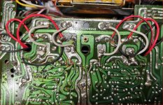
I have looked back through the thread to see if any detail might have been overlooked and arrived at images shown on post 32 on page 4 and post 7 on page 70 the last image after the first emitter resistor modification.
It appears that one of the driver transistors has a solder bridge between two of the leads. If so you need a solder sucker to remove it.
It is good practice to remove old solder rather than to reheat joints and remake them with fresh solder.
It is also bad practice to use solder as "glue" as this can conceal joints that have not set properly.
I appreciate there are places where there is no through the hole access from the top of the pcb and that is just part of the design which makes the job somewhat harder.
Attachments
- Home
- Amplifiers
- Solid State
- NAD 7020i sudden death