That is not likely to cause a reliability problem.I can keep my fingers on the heatsink even after playing music, but they sure are hot.
I have already mounted heatsinks (as stated earlier in this thread)
I guess I just don't really know what's 'working ok' hot and what's 'too hot' hot. Ian Finch's description of more than warm is about right though. I can keep my fingers on the heatsink even after playing music, but they sure are hot.
Because one of the heatshinks is for a different package I had to mount it horizontally.
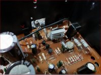
Comparing this shot with that in post 1, I noted Q413 the metal faces away from the heat sink.
In the present post the light is not good enough to see that the orientation is the same. I would have thought there should be some visible reflection from the metal.
Check the orientation of Q413 and Q414.
I only have a clear photo of the original: their position is mirrored (as all components for the two channels, except the transistors that are mounted on the heatsink).
In the last photos I posted you can somewhat see that one heatsink (the U shaped one) is bolted on one transistor's side towards the main heatsink (towards the left side of the amplifier), while the other is bolted on the opposite side (towards the right side of the amplifier).
It's just that the U shaped heatsink allowed me to mount it with the grooves oriented vertically, while the other one was quite a bit longer so I had to mount it with the grooves oriented horizontally (I don't know how much that actually matters from an air flow point of view - probably minimally in this case)
If you got the heat sinks on the metal side of the TO126 transistors of whatever number, and used heat transfer compound, that is about the best you could do. If the TO126 transistors were that F ceramic case with no metal, they are still more conductive than plastic case. If you didn't use heat sink compound that is still better than the nothing NAD installed.
The heat sinks you used were a lot bigger than the ones I put on the TO220 VAS & drivers in my ST120. Mine were about 1/2" long, made out of 5/8" aluminum channel with holes drilled in. The amp with those ran 14 hours a day every day for several years before a wire popped off and & started humming. Put wire back to "ground" but not the right one, apparently, still hums annoyingly. Peavey PCB's in $35 amps are an easier fix.
Only risk to your huge heat sinks, if you slam the amp around the transistors will break their legs. Not usually a problem in home service.
Last edited:
Let's use a simple reference for the temperature and make sure we understand what is referred to and the semis themselves are the correct type.
So, how does "more than warm" of Q411,413 compare to Q412,414 transistors in the other channel, whether they have heatsinks or not? You may not have any means of temperature measurement but there is an approximate reference at 60C where you can't hold your finger on the hot surface for more than a few seconds and some degree of injury. Otherwise, moisten your finger and smear that on the heatsink. If it makes a little steam and soon evaporates, its much hotter and if it hisses, splutters etc, its like 100C+. I've even seen candlewax used which is fine if you are familiar with its softening and melting point range.
60C is no problem for virtually any silicon semiconductor and other components too. These drivers should be fine and reliable up to 90C external temp. in appropriately designed applications so don't be concerned that semis should be cool and calm. They won't be when real power and bass grunt is needed. Their size and provisions for heatsinks is a hint of what their rated power dissipation means and they can dissipate 20W with heatsinks, 1W without. Either way, they can still become blistering hot on the surface. Inside, they can reach as much as 150C before serious damage occurs.
According to the 7020i service manual, the left channel (normally the top amplifier circuit on the schematic) has all parts with odd numbers. Its driver transistors, Q411 and Q413, are actually 2SD669A and 2SB649A. The right channel has corresponding even part numbers Q412 and Q414.
This scan may be easier to read than others: Free download Nad 7020 I Service Manual
Last edited:
I only have a clear photo of the original: their position is mirrored (as all components for the two channels, except the transistors that are mounted on the heatsink).
It is still possible to have the Q413 an Q414 facing in opposite directions and have the base and emitter connections transposed.
In post 1, Q413 has the rear with the metal strip facing toward the camera - in the opposite direction away from the main heat sink.
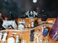
In the first image for post 100, looking at Q413, from an aspect similar to that in post 1, all you can see of this is black.
If the metal strip is on the opposite side of Q413 then both drivers have their base and emitter leads transposed.
Attachments
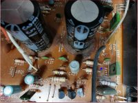
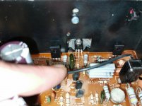
in this cropped version you can barely see a thin silverish line just above the heatsink.
but after Ian's post about temperature I'm not stressing over it anymore (I was mostly worried because those two transistors were the only ones that are getting a lot warmer than all the others. I'm sure the schematic itself has the explanation for that but since I can't really interpret it...)
but after Ian's post about temperature I'm not stressing over it anymore (I was mostly worried because those two transistors were the only ones that are getting a lot warmer than all the others. I'm sure the schematic itself has the explanation for that but since I can't really interpret it...)
Attachments
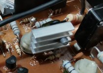
You are looking in the wrong place to see the point I was making. In post 1 Q413 side with the metal strip faced away from the main heatsink. In the image shown in post 106 it looks likely that the strip for the replacement Q413 faces towards the main heat sink.
If yes, then you will have to pull the drivers out of the board and look for any damage to these and other semiconductor components.
If yes, then you will have to pull the drivers out of the board and look for any damage to these and other semiconductor components.
oh, sorry! my mistake. I was stuck in the heatsink episode.
Q413 was originally a 2SB649A transistor and because I didn't find the same I went for KSA1220AYS as a replacement. It doesn't have a metal strip.
I still have the originals and they measured fine, but at that time I decided to replace all transistors in the power stage. When I finally started to work on the amplifier I did replace all transistors except for the three BCs (556B and 550C).
In that case the legend showing KSA1220AYS appears is on the side that faces the heat sink. I have some transistors in that style of case and it is hard to read the legend in reasonable light.
It may seem pedantic for me to ask you to check that, but trouble shooting is a case of leaving no stone un-turned - a process of elimination taking one step at a time.
Wholesale changing of transistors often makes trouble shooting a more lengthy process.
It may seem pedantic for me to ask you to check that, but trouble shooting is a case of leaving no stone un-turned - a process of elimination taking one step at a time.
Wholesale changing of transistors often makes trouble shooting a more lengthy process.

oh, sorry! my mistake. I was stuck in the heatsink episode.
Q413 was originally a 2SB649A transistor and because I didn't find the same I went for KSA1220AYS as a replacement. It doesn't have a metal strip.
I still have the originals and they measured fine, but at that time I decided to replace all transistors in the power stage. When I finally started to work on the amplifier I did replace all transistors except for the three BCs (556B and 550C).
Q405 and Q406 are the dynamic part of a VAS and these are BC556B.
Q407 and Q408 both BD139's are buffers
Q403 at the input is also a BC556B.
If the latter failed open circuit then Q401 would increase the bias on Q405 forcing this to pass more current and have the same effect on Q407.
Normally complementary feedback pairs have good thermal stability - these work by setting these up to counter balance - disturb this and the playing field can be tilted.
The worrying thing is that the increase in heat appeared in one of two channels and the problem appears to be present now in both.
I have no idea what the temperature of those BD139's was before the incident. When I bought the amplifier (about one or two months prior) I only opened it once to see what's inside (overall visual state of the capacitors, whether or not the outputs look to be original or if anything looks suspicious), so I wouldn't know if your last statement is correct or not.
I have to say that I didn't pull those BCs to test them but in-circuit they appeared to be fine. And I probably hesitated in replacing them because I only found the BC550 on Mouser. BC556 was out of stock and while I did buy some KSA992 (only based on one reply in a forum - might have even been here on DIY somewhere), I wasn't sure it's a correct replacement so decided to leave them alone.
But I could swap them if that's the way to go.
Same package (TO-126) different part # won't run cooler. Cooler than hot water 140 F is no unusually high temp on VAS or drivers. Heat dissipated is based on resistors of circuit, PS voltages, current demand of following transistor.
Fact that unit plays music provides pretty good indication you didn't install transistor backwards. Production substitutions Mr Finch discussed might mean OEM parts had printing on different sides than bc139/140 shown on schematic.
Way to really know if you have base in correct place is to buzz it to the output of the BC556 drivers. Complicated by the fact that there are 2 pinouts of BC556 drivers, European, and the opposite pinout used by US manufacturers. However the base of Q407 408 should buzz to R 435 436. That is left pin facing printing of BC139/140 with legs down. Center pin should buzz to R437 R438.
What I would do is check maximum power out on speaker terminal into 8 ohm resistors (or 8 ohm speaker) right before clipping. Specified power achieved, Q407 408 won't be backwards.
Hot drivers & VAS transistors are not unusual in home use market amps, and often lead to blowups. Reason I usually suggest home repairers put a little heat sink on them when they are in there, to stop from replacing them over again. PA equipment from reputable manufacturers (Crown, Peavey, QCS, Yamaha) have always had the heat sinks from the factory, the ones I've seen. Those 4 brands are touted by Pro repairmen on PA forum as having 24/7 power ratings. My sleazebag 1970 dynakit ST120 came from the factory with heatsinks on the VAS & drivers! Just the output transistor heatsink was totally inadequate for use longer than 1 hour FTC watts test.
Last edited:
Which schematic are you all referring to? The link at post #105 for example, is to NAD7020i and shows those Hitachi/Renesas drivers that the OP and I refer to. Perhaps you and mjona are looking at a much earlier NAD7020 schematic and finding BD139/140 there - not that it changes much in the overall plan but it does confuse some comments made here.
I feel it's a bit much for me and I wouldn't want to mess things up. Besides, I double checked all transistors before mounting, both with the data sheet and with a component tester (that automatically identifies transistor type, pinout, static beta etc).
I'm sure someone knowledgeable would certainly find further things to mend and adjust, but for the time being I believe it's beyond my understanding of electronics.
In the near future I'll do some A/B testing with all the gear I have and might even decide to sell the NAD if it falls short compared to either my other NAD (3240PE), a Kenwood KA 3700 or the Setton RS440 that are for the time being stacked in a closet 🙂
No problem, zenzaman. You are doing fine if you have satisfactory audio and the heat is comparable between channels. I was only asking mjona and maybe indianajo if we were all looking at the appropriate schematic.
All 7020 and 3020 series power amplifier schematics are are much the same but the small semis and a few component types change over the years of production. The 7020i schematic is not available at our popular source, hifiengine.com but legible scans can be found elsewhere.
All 7020 and 3020 series power amplifier schematics are are much the same but the small semis and a few component types change over the years of production. The 7020i schematic is not available at our popular source, hifiengine.com but legible scans can be found elsewhere.
Mine is the service manual for NAD7225pe and NAD7020i it is a case of discussions on separate tracks one following another.
With the latest images zenzaman posted it is easier to see the wider picture. From this and his comments the driver transistor discussion is closed.
With the latest images zenzaman posted it is easier to see the wider picture. From this and his comments the driver transistor discussion is closed.
I feel it's a bit much for me and I wouldn't want to mess things up. Besides, I double checked all transistors before mounting, both with the data sheet and with a component tester (that automatically identifies transistor type, pinout, static beta etc).
I'm sure someone knowledgeable would certainly find further things to mend and adjust, but for the time being I believe it's beyond my understanding of electronics.
You can do some post installation transistor tests with the amplifier powered up with no load or input to work out Vbe for each transistor. It is more accurate and safer to measure the base voltage and the emitter voltage separately with respect to earth.
The way I do this is to put the black probe in the black speaker terminal and measure with the red probe and then work out the difference by mental arithmetic. The result should be around 0.6V plus or minus.
If you have a lot of transistors to test you could draw up a suitable list with columns for description emitter voltage and base voltage and keep the record for reference and update if later you have to make some changes in the circuit.
I'll note this for the next time I open it up.
Anyway this whole adventure drew some of the NAD fanaticism away 🙂
Maybe there's just a whole lot of hype around some of the NAD models that isn't really supported by construction and sound. My plan is to use the A/B box to narrow the 4 amplifiers pile to one or two and then maybe keep an eye open for underrated, maybe broken amps. This way I can tinker from time to time and eventually find the combo that sounds best to my ears.
In the meanwhile I'd really like to thank you all. It would have been a much bumpier road without your input. Cheapeau!
- Home
- Amplifiers
- Solid State
- NAD 7020i sudden death