So im making a start on this as the 3020 i did was realy succesful
Bit more difficult with this one as there is no provision on the board for the TO-247 pattern, so im going to have to be creative
The circuits are very simlar in most ways to the 3020 so it should be straight forward in that sense, but not so in other ways
will progress updates as i go along 👍
Bit more difficult with this one as there is no provision on the board for the TO-247 pattern, so im going to have to be creative
The circuits are very simlar in most ways to the 3020 so it should be straight forward in that sense, but not so in other ways
will progress updates as i go along 👍

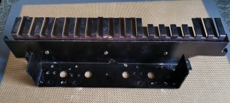
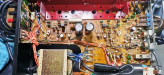
so the old heatsink is out and modified-ready to clean and have a light spray
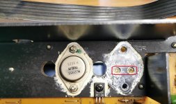
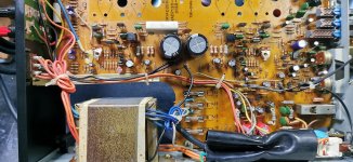
i will clean up, re cap and prepare the board while it is out-the burned area components are actualy ok, must be an old scorch mark
never seen these installed in a 3130 before
i will clean up, re cap and prepare the board while it is out-the burned area components are actualy ok, must be an old scorch mark
never seen these installed in a 3130 before
Attachments

Looking good. Some new caps in there I think. That 2043 opamp might be worth a play when its all done 🙂
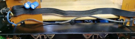
complete electrolytic recap. might as well while im doing this amount to the ampLooking good. Some new caps in there I think. That 2043 opamp might be worth a play when its all done 🙂
what would you do with the op amp then?
Knowing how you like to experiment with these things it might be worth trying something different (the 2043 is like a 4558 which isn't particularly great even though it is very common) but I see the supplies to it are in typical NAD fashion a bit weird. Nothing that can't be solved easily though. Maybe something like a an OPA2134what would you do with the op amp then?
well im up for trying things
as it happens i wanted to do this one without the VBE and drivers
it should work as it is very simplar to the 3020 we did
as it happens i wanted to do this one without the VBE and drivers
it should work as it is very simplar to the 3020 we did
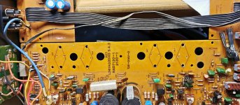
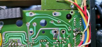
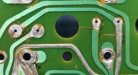
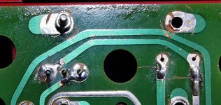
they do look like it, but to what end, not to seperate the print as the far righ one still has continuityThose look like knife cuts across the print to me
oh well they need to be repaired so thats the next job i think
as it happens i wanted to do this one without the VBE and drivers
We did a sim of the one with no drivers:
I would get it to work first with the multiplier, then think of removing that if you want. Ideally we fit a fixed resistor in its place because the current might be a bit high to feed into a preset wiper.
they do look like it, but to what end,
They definitely look like deliberate cuts to me. Scrape the lacquer and bridge with a cm or so of wire.
ok so keep the quasi pair ,ditch both the drivers, fit a 2K pre set and loose R459
i can see what your doing here, i think it should be easy enough, just a few links
i can see what your doing here, i think it should be easy enough, just a few links
Last edited:


just check i have this correct
That looks correct. Remember the multiplier has to be set to give minimal voltage between the gates. Do as we did on the one you have already done, and I can't remember what val;ue preset you used for RX1 but around 2k sounds in the right ballpark so perhaps a 2k2 or 4k7 preset for RX1.
If you use the bulb then provided the FET's are fitted correctly they will be safe.
the paint is very thin, but it is metal flake paint so it conducts realy well, but you are right, if it is too thick it would have an affect, not sure how much thoughNice project but paint on the heatsink on the contact surface of the mosfet ?
Doesn't it reduce the heat transfer ?
Just asking out of curiosity.
- Home
- Amplifiers
- Solid State
- NAD 3130 conversion to Lateral FET