i used 1k in the other ampThat looks correct. Remember the multiplier has to be set to give minimal voltage between the gates. Do as we did on the one you have already done, and I can't remember what val;ue preset you used for RX1 but around 2k sounds in the right ballpark so perhaps a 2k2 or 4k7 preset for RX1.
If you use the bulb then provided the FET's are fitted correctly they will be safe.
If we go with no drivers then the voltage across the multiplier needs to be lower still by what would have been the two Vbe volt drops of the driver pair. The lateral FET's will bias up with only around 1 volt between the two gates.
The other option is to use no multiplier at all and use just a trimmer (something like a 220 ohm) and having set the bias we remove the trimmer carefully, measure it and fit a suitable resistor or resistors to get the value needed.
The other option is to use no multiplier at all and use just a trimmer (something like a 220 ohm) and having set the bias we remove the trimmer carefully, measure it and fit a suitable resistor or resistors to get the value needed.
It would look like this. Value to be decided at the time but something low like a 47 ohm should work from the start.

Lets get it working first although the multiplier is a very small part of it all. It's easy to implement whatever scheme you want.
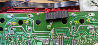
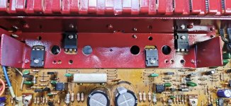
ok so now all 4 FETS are dry fitted and as you can see there is plenty of room for the legs now.
Now we get to work on how they will connect underneath
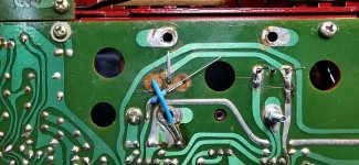
The gates are easy, straight forward solder onto original base positions
The source connections are also easy, much easier on this amp, as the 3020 had the solered connections already in place to take a T0-247 type arrangement, so i dont need to sleeve this one
The drains are a different matter, they have to be soldered to the original collector feeds, so not only does it need to be sleeved but isolated from the package mounting screws
They will of course be mounted on insulating pads and paste and the screws themselves sleeved
Now we get to work on how they will connect underneath
The gates are easy, straight forward solder onto original base positions
The source connections are also easy, much easier on this amp, as the 3020 had the solered connections already in place to take a T0-247 type arrangement, so i dont need to sleeve this one
The drains are a different matter, they have to be soldered to the original collector feeds, so not only does it need to be sleeved but isolated from the package mounting screws
They will of course be mounted on insulating pads and paste and the screws themselves sleeved
Attachments
That looks like it will all end up neatly done.
Just be 100% of your connections... I know you have done one before... check check and check again. I'm not saying that because I think there might be a problem, its just because you have the real board and parts in front of you and can see how it all comes together 🙂
Just be 100% of your connections... I know you have done one before... check check and check again. I'm not saying that because I think there might be a problem, its just because you have the real board and parts in front of you and can see how it all comes together 🙂
You mean the middle pin of the FET's, the Source? Those would have been the emitter of the NPN/PNP original output pair which were joined. So yes, the source of the FET's join and that should be the output line. The drains go to the supply. Check check and check again before applying any power. Make absolutely sure you have the correct FET in the correct location... its just so easy to get bamboozled with things like this.
Remember to fit the gate stopper resistors close up to the gate pin of the FET as possible which you look to have done 👍

Remember to fit the gate stopper resistors close up to the gate pin of the FET as possible which you look to have done 👍


anyway im about done for tonight
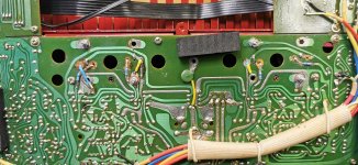
all i need to do now is final checks and fit the pre sets
all the continuities check out, no shorts anywhere
all i need to do now is final checks and fit the pre sets
all the continuities check out, no shorts anywhere
Right, I see what you mean now.black line, they would have been connected by the case
- Home
- Amplifiers
- Solid State
- NAD 3130 conversion to Lateral FET