All that is left to do for now is fit the pre sets and it should be (after checking it All again) ready to turn on to look at voltages once I know all is ok and it works like this we will try the mod without the VBE
for now yes, but the plan is actualy to try it both ways, so first with the VBE removed, then the drivers
I want to be sure the amp works ok first
I want to be sure the amp works ok first
That all sounds promising. Providing the heat dissipation feels OK you can (ideally) run the FET's at around 100ma. That would be about optimum but if they feel to hot (because of limited heatsinking) then you can come down a bit. No issues with thermal runaway with Lateral FET's as they have a negative temperature coefficient which means the current has a tendency to fall as they heat.
As you are experimenting with this it would be worthwhile you making a note of the exact voltage between the gates (measure not directly between the gate pins but instead between the two gate resistors at the multiplier end... its safer for the FET's measuring that way). There is no volt drop lost across those gate resistors.
Measure this voltage at the bias current you wish to use.
Knowing that value might make it easier to calculate straight off the required single resistor value needed in place of the multiplier.
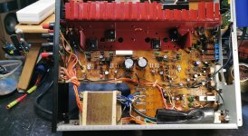
We would also need to know the voltage across the resistor marked here. Knowing all that we can easily calculate the single value needed for your chosen bias current.

Measure this voltage at the bias current you wish to use.
Knowing that value might make it easier to calculate straight off the required single resistor value needed in place of the multiplier.
We would also need to know the voltage across the resistor marked here. Knowing all that we can easily calculate the single value needed for your chosen bias current.

at these settings the fets are pretty cool (28c) and the heatsink is cool as well so the current can be increasedThat all sounds promising. Providing the heat dissipation feels OK you can (ideally) run the FET's at around 100ma. That would be about optimum but if they feel to hot (because of limited heatsinking) then you can come down a bit. No issues with thermal runaway with Lateral FET's as they have a negative temperature coefficient which means the current has a tendency to fall as they heat.
so no voltage drop at all 847mv both sidesAs you are experimenting with this it would be worthwhile you making a note of the exact voltage between the gates (measure not directly between the gate pins but instead between the two gate resistors at the multiplier end... its safer for the FET's measuring that way). There is no volt drop lost across those gate resistors.
Measure this voltage at the bias current you wish to use.
Knowing that value might make it easier to calculate straight off the required single resistor value needed in place of the multiplier.
We would also need to know the voltage across the resistor marked here. Knowing all that we can easily calculate the single value needed for your chosen bias current.
View attachment 1137416
between gates 840mv (VBE end of resistor)
so set at 100mv i get a weird buzzing out of the speakers
when you say idealy at (100ma) how are you measuring this on the amp
when you say idealy at (100ma) how are you measuring this on the amp
Brilliant 👍so version one complete-sounds realy good
at these settings the fets are pretty cool (28c) and the heatsink is cool as well so the current can be increased
That's up to you. 28C is nothing.
so no voltage drop at all 847mv both sides
between gates 840mv (VBE end of resistor)
That sounds about right. If we also know the voltage across that 1k2 I circled we can get close to the correct value of single resistor needed in place of the multiplier.
so set at 100mv i get a weird buzzing out of the speakers
when you say idealy at (100ma) how are you measuring this on the amp
I assume you are measuring this across the 1 ohm test resistor.
The buzzing could be a number of things, even using a bulb tester might do that as the supplies will fall a little and any regulated supplies might drop out of regulation. To trace it you need to use the scope. Look what the buzz actually is. 50Hz, 100Hz or something else? and also look at the rails.
I'd say you need to look with the scope and see what the buzz actually is. You also need to isolate the power amp from the preamp.
If it varies as you increase the bias current then it sounds like rail ripple getting in somewhere. Obviously it shouldn't do that but don't assume it is a problem caused by the FET mod. It may do/have done the same as standard if the current was increased the same way.
As always... measure and test and gather evidence.
so with the left channel set at around 26mv and ramping up the right to over 200mv, there is no buzzing, the minuite i start to increase the left higher its like an oscillating noise, rather than a buzz
could it be a dodgy ceramic cap somewhere breaking down
could it be a dodgy ceramic cap somewhere breaking down
So the problem is just on one channel.
It could be anything but I wouldn't immediately suspect a cap breaking down. The DC conditions across any of the caps doesn't change as you increase the current. I think you are going to have to look with the scope and see what this noise looks like. Big clues are whether it is harmonically related to the mains frequency or not.
Make sure the DC offset remains low as you increase the current.
Make sure the 1 ohm is actually OK and not high in value as can happen if there has been a previous fault and overload.
what is odd is the amp works perfectly fine set at 30mv, no noise, no buzzing, nothing
centre is unaffected by any adjustment
both 1ohm's fine, i checked them earlier
centre is unaffected by any adjustment
both 1ohm's fine, i checked them earlier
Well that sounds unusual. I think I would still want to know what the noise is though. The scope will tell you if it really is some genuine instability or oscillation or if it is just a mains (ripple) related issue. Both channels should behave in the same way of course.
You've kept the drivers with this one... up to now anyway... yes?
I loose track of where you are up to 🙂
You've kept the drivers with this one... up to now anyway... yes?
I loose track of where you are up to 🙂
- Home
- Amplifiers
- Solid State
- NAD 3130 conversion to Lateral FET