so no difference with those removedThe output inductor is there to isolate the output stage from any unintended capacitive loading (such as the self capacitance of some speaker cables) which can cause oscillation and instability.
The thing with your noise is that you describe it as buzz which means low frequency, perhaps a few tens or hundred Hz but no higher.
Your scope shots don't seem to show anything like that. What you really need to do is set the timebase to a slower speed such as 5 or 10 milliseconds per division and see what this buzz looks like at that sort of speed.
Try removing those caps I circled to see if the soft clip is feeding anything rail related into the amp. Keep using the bulb for safety though.
I have also gone through each cap i replaced to ensure all were the correct values and voltages/polarity and they are all correct
Fair enough, it eliminates that area of the circuit.
This buzz is audible of course. We need to see a scope shot of that noise and that means using a slow timebase speed which you might have to set manually. We need to see what we are chasing here.
Get it making the noise and put the scope across the output. Set the timebase to 10 milliseconds/div initially and see what shows up. A low level buzz could be only a few tens of millivolts in amplitude. So set the scope manually to look for something like that rather than letting it auto range on something that might not be an issue.
This is from a simulation but shows what a typical annoying buzz might look like. Frequency is 100Hz (mains related) and amplitude low. Use that as a starting point.
Our hearing is insensitive at low frequencies, so the buzz voltage should be large enough to be easy to measure
this is with zero current applied, either channel
Attachments
Last edited:
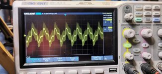
That looks like oscillation sat on top of mains related ripple. The slow timebase shows the low fundamental but all the fine 'grass' riding along with it looks like high frequency noise. If you wind the timebase out (faster) you lose the fundamental and begin to see just the high frequency stuff.
The low frequency ripple is getting into the amp somewhere. I would next measure the supplies with the scope (same timebase setting and with AC coupling and look at the amplitude of the ripple on the rails. All the rails related to the power amp.
The high frequency noise would have to be looked at separately I think. If you have another similar non modified amp it might be worth comparing against using the scope.
It would be worth looking to see how it compares. Make sure the test set up is identical in every way. Just substitute the amp. All leads and wires/probes/ground points etc to be the same.
so im going to have to be carefull with the standard one as ive just repaired it lol and dont want to have to do it again
its going to get pretty hot, pretty quickly if i stick the current up to 100ma, so i will need to be quick
its going to get pretty hot, pretty quickly if i stick the current up to 100ma, so i will need to be quick
so im not going to start messing about with the standard one as it has no pre sets on the VBE and i dont want to start playing around with resistor values.
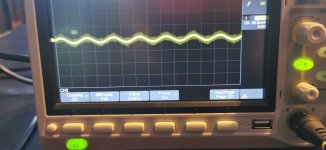
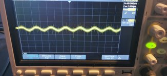
I do have another of these and when i get it out ill fit some pre sets to it, but for now the attached comparison is at a fixed 27mv across the 1ohm
1st pic is standard left channel
2nd pic is standard right
3rd pic is modified left
4th pic is modified right
All at the same current settings
as you will see there isnt alot of difference,unless you see things differently to me.
maybe it just is what it is and going to high with the current will amplify what is already there
Attachments


Very interesting. thanks.
I would agree they look similar so maybe it is 'just how they are'.
One easy thing to try with either amp. Use the same test setup but this time clip the probe ground to the probe tip... and you should get a clean straight trace of course. Now touch the still joined tip and ground lead to the same ground point you used in the measurements. The trace should still be a totally clean and straight.
If its not then artefacts of the test set up and grounding are coming into play,
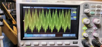
This might help you understand how the scope looks with a low and a high frequency signal together.
Run the sim and you will see a 50 Hz 1 volt sine and a 1Mhz 50 millivolt sine superimposed on it. Look at the units at the bottom (timebase speed). F=1/T remember and so we can look and see that 1 cycle takes 20ms. 1/0.020 =50Hz
Now place the cursor over just above any part of the green trace and then holding the left click button down draw a tiny rectangle over that part of the trace. The trace will expand. Keep doing that again and again and it zooms in on on that area. Look at the units at the bottom.
You now have no clue about the 50Hz, all you see is the high frequency part.
Pick any two parts of the waveform where it repeats and work out the time for 1 cycle. In the last image I see 44.9470ms and 44.9480 as convenient points to read off values. 44.9480ms-44.9470ms = 1us (1 microsecond)
F=1/T which is 1/1E-6 which is 1000000Hz or 1Mhz.
Attachments
so what would harmonic distortion look like on a scope? or can you not see as such on the scope
It doesn't show up mostly on a scope, not at low distortion levels anyway. Exceptions are crossover distortion which is easily seen if its even if its only moderately bad. You can also detect 2nd harmonic distortion by asymmetry in a sine wave although it still has to be quite high to do that.
so how do you actualy measure harmonic distotion, because the human eye is limiting isnt it, especialy as it get older, so to do a real comparison when changing things it needs to be measured to be proved?
You should really measure it with test equipment designed for the job. You need to remove or 'notch out' the fundamental test frequency (say 1kHz) and look at what is left, what the amp has added itself. We could do it with diy gear back in the day (analogue filters to remove the fundamental) but things have got more sophisticated now.
I think your scope might have an FFT (Fast Fourier Transform like in LTspice) function which in theory shows the fundamental and the harmonics but it might be very limited in its abilities.
I think your scope might have an FFT (Fast Fourier Transform like in LTspice) function which in theory shows the fundamental and the harmonics but it might be very limited in its abilities.
- Home
- Amplifiers
- Solid State
- NAD 3130 conversion to Lateral FET