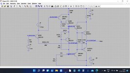
so the transistors i changed yesterday,Q409 and Q410 are the multipliers? and the drivers Q406 and Q408?
Q406 and Q408 are the VAS or voltage amplifier stage. Q410 is the multiplier and Q412 and Q414 the drivers.
Q406 and Q408 are the VAS or voltage amplifier stage. Q410 is the multiplier and Q412 and Q414 the drivers.
ive not got long today, people coming round, but i have checked all the transistors apart from Q404 and Q402(i can if you think it is worth doing) and all of them are fine.
one thing i havent worked out yet is R 450 seems to be quite important as ,if im reading it right, should be 33ma across it, or am i reading it wrong
well neither channel has that, the faulty one is 180ma and the other channel is 110ma across it.
R446 ,450,452,460,462,454 all check out fine
The only things i havent checked now are the small value film and ceramic caps, which rarly fail,but of course could.
all i can do now is work further back
Lets stick with this and be sure we both know what is going with those measurements.
Also I made an error in the sim with connection of that 33 ohm. It doesn't affect the voltages but it means the bias set resistor needs altering on the sim. The 33 ohm is used to modify the temperature response of the multiplier so it tracks bias current vs temperature more accurately.
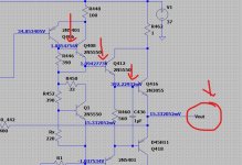
Look at the picture. If you have 2.63 volts on the multiplier collector and 0.144 on the output then I would suspect (in the sim) that Q412 was faulty.
Also I made an error in the sim with connection of that 33 ohm. It doesn't affect the voltages but it means the bias set resistor needs altering on the sim. The 33 ohm is used to modify the temperature response of the multiplier so it tracks bias current vs temperature more accurately.
only real difference is, if it matters is the collector voltages- on Q409 its 2.63V and on Q410 its 1.13v
also the base voltages on both of these are only 560mv
Look at the picture. If you have 2.63 volts on the multiplier collector and 0.144 on the output then I would suspect (in the sim) that Q412 was faulty.
Attachments

so this is the actual, as the amp is currently
ive altered the sim voltages to what they actualy are and the strange thing is the sim voltages are almost correct to what the faulty channel is, not the one that is working correctly, does that make sense
so this is what i took this morning with the soft clip on
R448 100ohm -35.53v in -35.49v out resistor fine 1 leg pulled
Q406 -faulty channel transistor checks out ok out of circuit
B -33.87v
E -34.50v
C -1.90v
R449 100ohm -35.53 in -34.33 out resistor fine 1 leg pulled
Q405-good channel transistor checks out ok out of circuit
B -33.75v
E -34.35v
C -3.36v
so im a bit confused with both R448 and R449 being good why the outputs of each one are different
Attachments
R448 100ohm -35.53v in -35.49v out resistor fine 1 leg pulled
So you are saying there is just 0.4 milliamps flowing in that resistor. I=V/R which is 0.04/100 giving 0.4 milliamps.
So this is another reading that at face value shows a problem.
Look at the circuit and try and follow this reasoning...
If the midpoint voltage is anywhere close to zero then we can say with certainty that the voltage on the driver transistor bases will also be 'close' to zero.
Look at R456 and R458, the 1k2 reistors. These are in series and so make a 2k4 as far as DC analysis goes.
So we should have supply on one end of the resistor (-37 v or whatever it is) and 'close to zero' on the other. The current should be I=V/R which is 37/2400 giving 15 milliamps.
And there is the problem 🙂 The 15 milliamps is a certainty and that current should also flow in the 100 ohm... and it is not apparently doing so.
So again there is a discrepancy between expected results and what you seem to measure 🙂
So we now have two weird results that all centre around that driver stage.
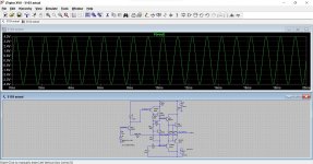
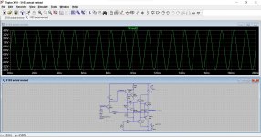
Your attached sim can be made to work dynamically. You need to change the voltage source to an AC one and tweak the DC shift of the input.
You will see that as it stands now, the voltage gain is '1'. So voltage in equals voltage out approximately.
Make the sim run to just 100ms and start saving data at 80ms.
Edit... I've made the input 4 volts here, not 0.1 as shown.
You will see that as it stands now, the voltage gain is '1'. So voltage in equals voltage out approximately.
Make the sim run to just 100ms and start saving data at 80ms.
Edit... I've made the input 4 volts here, not 0.1 as shown.
Attachments
so a correction on the previous-in bold
R448 100ohm -35.53v in -34.49v out resistor fine 1 leg pulled
Q406 -faulty channel transistor checks out ok out of circuit
B -33.87v
E -34.50v
C -1.90v
R449 100ohm -35.53 in -34.33 out resistor fine 1 leg pulled
Q405-good channel transistor checks out ok out of circuit
B -33.75v
E -34.35v
C -3.36v
I have my old original 3130 upstairs that is in perfect working order so im going to open that up and compaier a few things
so straight away there is a problem, with under supply voltage
so my old one supplies 37v to that region and across R448 -37.2v in -36.0 out and R447 the same
Last edited:
That looks more reasonable for the 100 ohm. So about 11 milliamps flowing. That is in the right ballpark given your supply and a couple of other factors (the vbe volt drops I did not include before as it was an approximation).
Transistors can do strange things when you heat them to remove them so I wouldn't be convinced at this stage.
The real test really is the voltage measurements when it is operating. Remember when I said to use the output line as a reference point at work forwards from there. That would show any problems.
If you put your black meter lead on the output and then measure you should see this progression as each reading adds a new base/emitter volt drop to the one before.
The PNP lower half would do the same except now the voltages would be negative.
Attachments

Besides keep getting it wrong you mean 😀
I'm trying to do a zillion things at once at the moment. I shall amend my sim.
I'm trying to do a zillion things at once at the moment. I shall amend my sim.
does it matter that R454 (in parallel with RX2)(180ohm) is missing from the sim?
see comparison
It doesn't matter in simulation because this is a resistor chosen on test. All that matters is the value of resistance between B and E of the multiplier and in simulation will be very different to a real design due to differences in transistor parameters.
If you change the multiplier transistor in the sim you will get wildly different bias current flowing (in the 1 ohm test resistor). In the revised sim above it is set to about 46ma. Change the transistor to a 2N3391A and it falls to 3 milliamp so you would need to tweak that resistor again.
i think i am just about ready to give up on this for now i have had every single component out and checked, and replaced (Q412)
outputs-Q416 and Q418 are the only ones that havent been out.
i even replaced C416,418 and C434.
time to walk away for a bit with this me thinks AS I AM VERY 😕 right now
outputs-Q416 and Q418 are the only ones that havent been out.
i even replaced C416,418 and C434.
time to walk away for a bit with this me thinks AS I AM VERY 😕 right now
Well you can put it away for while but don't give up 🙂
Come back to it fresh, build the amp up with all the parts in place and start again. Concentrate on one fault only and follow the diagnostics properly. Measurement is key, taking parts out and refitting them can lead to all sorts of problems.
Come back to it fresh, build the amp up with all the parts in place and start again. Concentrate on one fault only and follow the diagnostics properly. Measurement is key, taking parts out and refitting them can lead to all sorts of problems.
oh i wont give up,but its hot,im hot and i think ive had one of those round in circles moments.
ill come back and take a look at it from scratch.
ill come back and take a look at it from scratch.
- Home
- Amplifiers
- Solid State
- nad 3130 Centre voltage adjustment issue