not sure if this is significant or not
ive been checking and recording voltages of all the components starting from VR402, all the resistors, and capacitors through Q402 and Q404
They are all pretty much the same values more or less, until that is untill you come to C414, which you mentioned removing in a previous part of the post.
now i replaced this but tonight when i was checking all the voltages i noticed one difference-C414
on the good channel the possitive side of the cap (C414) -1.068v
neg side 0.111v
on the faulty channel the possitive side of the cap(C414) -1.068v neg side of the cap 2.13v
that makes the voltage drop across D408 375mv is that right? (2.49v possitive side of C426)
Last edited:
Any unexpected results always need checking, either to show a problem exists or perhaps that it doesn't.
No electrolytic should be reverse biased and so something seems amiss. Both those readings show the caps are reverse biased. The first thing to check therefore is whether the cap is right way around. The positive end should go to the base of the transistor. It is not unknown for board marking to be in error. The circuit diagram is correct though. + end to base.
Lets go back the clip circuit and look at the DC conditions.
I would remove C414 while you test all this. If it is reverse biased it will be leaking current and confusing reading even more. So just pull it out.
With the cap out recheck the voltage across where the cap would have been and confirm it it still of the wrong polarity.
Also 🙂 just make sure you have your meter leads plugged into the meter the right way around. It's hard to see both channels being wrong like this.
my leads are def the right way round, i think i would know if they were not.
i have checked the voltages and they are correct
i wont pull it out tonight as i got to go out in a bit, but i have double checked all i have done and all of the readings are correct.
just as a note, the opposite diode D407 -1.594v/-0.103mv
so i took that cap out and there was no change in the voltage readings, but with it out the sprurious voltages have ceased
Last edited:
.........that makes the voltage drop across D408 375mv is that right? (2.49v possitive side of C426)
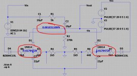
It doesn't sound right. The ends of the two diodes that go to R424 (270k) should always be at zero volts DC.
Make sure you remove C414 for measuring all this though.
The other end of the diodes, so the ends that go to C426 and C428 have a voltage that depends on the switch setting but I'm seeing 1.5 and 5.5 volts there. One side is negative and one positive.
So those two voltages would be the voltages expected across the diodes.
Important so your 375mv suggests a diode that is fitted the wrong way around. Make sure both of those diodes are fitted correctly. Normally they are always reverse biased.
Look at the three voltages here. The switch is open.
The diodes are reverse biased and so can allow the voltage across them. The top end of both diodes is or should always be zero because it is ground referenced by the 270k.
Check it all carefully. I'll look in again tomorrow.
The diodes are reverse biased and so can allow the voltage across them. The top end of both diodes is or should always be zero because it is ground referenced by the 270k.
Check it all carefully. I'll look in again tomorrow.
Attachments
i checked last night, and both diodes show(on the board anyway) that they are the right way round
should i spin one or the other and see what happens.?
i have left that cap out for now.
they look the same on the other circuit, and that one seems ok
i have been logging all the comparatives on 2 separate diagrams which i can scan in later when i get home if you want to see them, but they are all pretty close up to C414
the only other possibility is the Clip switch itself, maybe the little sprung sliders have moved on one side, but it is unlikely.
No, lets prove what is happening and why you see what you do. This is where fault finding gets really interesting... its all about gathering evidence.
Leave the cap out and lift one end of each of the two diodes to isolate them.
Switch on and measure the voltage on C428. It should be negative and either around -1.5 or -5.5 depending on the switch position.
Now measure on C426 and you should see very similar voltages but this time positive.
Now measure and confirm that you have a true zero volts on R424
Lets get it to that point first.
OK. Try and understand the method 🙂
Look at the circuit. The diodes should not be conducting at all meaning whether they are fitted or not they should not change those two voltages (the 1.5 and 5.5).
So the diodes should have those same voltages across them and not the 375mv you measured on one of them.
So this should prove what is happening and why.
yep i understand the reasons for taking them out of circuit
you want this with/without the clip on? or both? as it will take R426 out of the equation with it on.
you want this with/without the clip on? or both? as it will take R426 out of the equation with it on.
Last edited:
Do it with the clip both on and off, lets see what voltages you actually have on C426, C428 and R424.
No, lets prove what is happening and why you see what you do. This is where fault finding gets really interesting... its all about gathering evidence.
Leave the cap out and lift one end of each of the two diodes to isolate them.
Switch on and measure the voltage on C428. It should be negative and either around -1.5 or -5.5 depending on the switch position.
Now measure on C426 and you should see very similar voltages but this time positive.
Now measure and confirm that you have a true zero volts on R424
Lets get it to that point first.
1 leg lifted on each side of D406 and D408
so prob not what you are going to expect
SOFT CLIP ON
C428
neg side +3.924v
poss side 0v
C426
neg side 0v
poss side +2.48v
R424 0v both sides
SOFT CLIP OFF
C428
neg side +5.80v
poss side 0v
C426
neg side 0v
poss side 0v
R424 v both sides 0V
Last edited:
Very interesting and not what I expected at all.
The good thing is it shows a problem but I can't see what... so we need to look a bit closer.
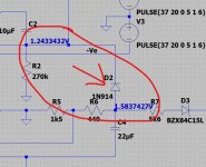
Here is the reasoning. That last result of Soft Clip OFF and you having C426 with both sides at zero volts suggests that R434 is either open circuit or very high in value. That is the only thing that could cause no voltage on the cap in that configuration. That is a big big clue here.
The puzzle is that C428 negative terminal would rise to about 5.8 volts but it would be negative, not positive.
And more odd, with soft clip on you would see the voltages you mention but with opposite polarity.
So lets just do the obvious thing at this point and remove and measure R434
The good thing is it shows a problem but I can't see what... so we need to look a bit closer.
Here is the reasoning. That last result of Soft Clip OFF and you having C426 with both sides at zero volts suggests that R434 is either open circuit or very high in value. That is the only thing that could cause no voltage on the cap in that configuration. That is a big big clue here.
The puzzle is that C428 negative terminal would rise to about 5.8 volts but it would be negative, not positive.
And more odd, with soft clip on you would see the voltages you mention but with opposite polarity.
So lets just do the obvious thing at this point and remove and measure R434
Very interesting and not what I expected at all.
The good thing is it shows a problem but I can't see what... so we need to look a bit closer.
Here is the reasoning. That last result of Soft Clip OFF and you having C426 with both sides at zero volts suggests that R434 is either open circuit or very high in value. That is the only thing that could cause no voltage on the cap in that configuration. That is a big big clue here.
The puzzle is that C428 negative terminal would rise to about 5.8 volts but it would be negative, not positive.
And more odd, with soft clip on you would see the voltages you mention but with opposite polarity.
So lets just do the obvious thing at this point and remove and measure R434
R434 on the money.
Very interesting and not what I expected at all.
The good thing is it shows a problem but I can't see what... so we need to look a bit closer.
Here is the reasoning. That last result of Soft Clip OFF and you having C426 with both sides at zero volts suggests that R434 is either open circuit or very high in value. That is the only thing that could cause no voltage on the cap in that configuration. That is a big big clue here.
The puzzle is that C428 negative terminal would rise to about 5.8 volts but it would be negative, not positive.
And more odd, with soft clip on you would see the voltages you mention but with opposite polarity.
So lets just do the obvious thing at this point and remove and measure R434
as a direct comparison
SOFT CLIP ON
C425
neg side 0v
poss side -1.735v
C427
neg side 1.81V
poss side 0V
SOFT CLIP OFF
C425
neg side 0v
poss side 6.17v
C427
neg side 6.21v
poss side 0v
Excellent 🙂 so all good now?
You see how being methodical and gathering all the evidence works. You have to measure and analyze and then try and figure out what is going on.
You see how being methodical and gathering all the evidence works. You have to measure and analyze and then try and figure out what is going on.
no not at all, what i just showed you was the opposite channel, i also got out a good one i have repaired and the voltages are almost identical to the good channel on both sides, so i still have to establish what is wrong with the faulty one on this amp.
the neg readings should be possitive and visa versa
that will have to be tomorrow now, TV time🙂
the neg readings should be possitive and visa versa
that will have to be tomorrow now, TV time🙂
- Home
- Amplifiers
- Solid State
- nad 3130 Centre voltage adjustment issue