no the resistor was all good @270k
i still have a bee in my bonnet about the switch, so just to satisfy my own mind im going to change one tomorrow
but it cant be mutch and must be staring in the face, i recon not too far away.
i still have a bee in my bonnet about the switch, so just to satisfy my own mind im going to change one tomorrow
but it cant be mutch and must be staring in the face, i recon not too far away.
that will have to be tomorrow now, TV time🙂
Same here. Last part of 'Finding Alice' recorded a while back.
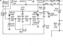
bugs me when i make a mistake, but happy when someone else is right. R434 open circuit, replaced, all other parts back in and centre voltage stable clip on or off 🙂
took a while this one, next time i will start at the other end 😀
cheers once again. it was a real challenge this one 🙂
took a while this one, next time i will start at the other end 😀
cheers once again. it was a real challenge this one 🙂
Wonderful 🙂 its good when a plan comes together.
It might be worth you checking the other 5k6 although if the voltages are symmetrical on the resistor network then it will be OK.
It might be worth you checking the other 5k6 although if the voltages are symmetrical on the resistor network then it will be OK.
so its been on for half an hour now and both channels are exactly -1mv (R) and 0mv(L)
ill use it for a week before im happy its ok.
im going to check the voltages again later today just to make sure as that polarity thing was weird, but for now ive got an injured hedgehog to deal with and get to hospital, so off to leatherhead before work.
ill use it for a week before im happy its ok.
im going to check the voltages again later today just to make sure as that polarity thing was weird, but for now ive got an injured hedgehog to deal with and get to hospital, so off to leatherhead before work.
Sort the hog first 🙂
Its worth going back over the voltages across the caps and seeing why you measured the polarities as you did.
The fault is a definite, there will be no contributary causes to that resistor failing. Its a one of genuine fault, the best kind.
Its worth going back over the voltages across the caps and seeing why you measured the polarities as you did.
The fault is a definite, there will be no contributary causes to that resistor failing. Its a one of genuine fault, the best kind.
R434 open circuit, replaced, all other parts back in and centre voltage stable clip on or off 🙂
If a resistor isn't burned you just don't expect it to be open circuit, but very occasionally it does happen. Well done!
Sort the hog first 🙂
Its worth going back over the voltages across the caps and seeing why you measured the polarities as you did.
The fault is a definite, there will be no contributary causes to that resistor failing. Its a one of genuine fault, the best kind.
Hog delivered
so final set of recordings, appears all normal
centre voltage 0v +/-1mv
idle 28mv on both
soft on
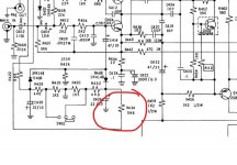
C428
poss 0v
neg +1.71
C426
poss -1.56v
neg 0v
soft off
C428
poss 0v
neg +5.85v
C426
poss -5.70v
neg 0v
🙂
I'm sure it will be right but I struggle understanding your readings tbh 🙂
Lets pick a cap, say C428. The positive terminal is grounded according to the diagram. So that means we should always see 0V there and that is what you report
Then you say neg +1.71 volts 😕 😀
The neg end of the cap should have negative 1.71 volts on it if you measure from ground. So the black meter lead goes to ground for the measurement.
If a cap is floating within a circuit such as C414 then it can be easier to measure across the cap itself placing the meter leads to match the cap markings polarity. That way if you read a positive voltage you know it is OK. Anything negative means a problem.
The above method works just as well for ground referenced caps. Done that we you would or should always see a positive voltage across every electrolytic cap. Measuring from ground may give a positive or negative result depending on the circuit.
So you see 🙂
Attachments
i was born to confuse😱I'm sure it will be right but I struggle understanding your readings tbh 🙂
Lets pick a cap, say C428. The positive terminal is grounded according to the diagram. So that means we should always see 0V there and that is what you report
Then you say neg +1.71 volts 😕 😀
The neg end of the cap should have negative 1.71 volts on it if you measure from ground. So the black meter lead goes to ground for the measurement.
If a cap is floating within a circuit such as C414 then it can be easier to measure across the cap itself placing the meter leads to match the cap markings polarity. That way if you read a positive voltage you know it is OK. Anything negative means a problem.
The above method works just as well for ground referenced caps. Done that we you would or should always see a positive voltage across every electrolytic cap. Measuring from ground may give a positive or negative result depending on the circuit.
So you see 🙂
C428
poss 0v
neg -1.71
C426
poss 1.56v
neg 0v
Last edited:

yep been using it all day.been an interesting one this, and i have learned alot,including it pays not to go round in circles,but to step back and take a fresh look so all been worth it 🙂
Absolutely. It really is all about evidence gathering, and that to me is what makes fault finding so interesting.
- Home
- Amplifiers
- Solid State
- nad 3130 Centre voltage adjustment issue