are some of the resistors purposly the wrong way round?
shouldnt the current values be the same on C3 and C4
and shouldnt the output voltage be the same as the input but clipped?
I never pay attention to component direction in sims tbh, it never causes any problems in practice... at least for everything I have done 🙂
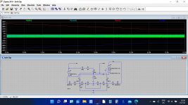
As the input voltage rises a point is reached where clipping occurs. So below this point Vin and Vout are the same. Make the amplitude 2 volts and compare. They are the same.
Now make it 2.2 and a little soft clipping occurs. The input voltage can not exceed this level and so the amplifier itself is protected from clipping.
Amplifying a clipped signal is totally different to have an amplifier do the clipping which can result in all kinds of unwanted behavior. The clipped input signal is totally valid as far as the amp is concerned.
So the way i see it is that the only parts in play that could be at fault are R426 and R430 because they are bypassed with the switch?
unless there is a problem with the switch itself maybe as it is double pole
unless there is a problem with the switch itself maybe as it is double pole
The basic checks are to see each Zener has 15 volts across it. With the soft clip turned on check that you have about +1.5 volts on C426 and -1.5 volts on C428
With the switch open the soft clip actually still works, it is just the levels needed to operate are now so high that it effectively may as well not be there.
The 440 and 1k5 resistors just set the DC reference points on the diodes.
Make sure the Zeners are the right way around and make sure the 1N4148 are the right way around.
The 440 and 1k5 resistors just set the DC reference points on the diodes.
Make sure the Zeners are the right way around and make sure the 1N4148 are the right way around.
I'd take a look at the soft clipping switch as well - according to the schematic, the same switch is used for both audio channels, and for switching power to the D411 LED.
The basic checks are to see each Zener has 15 volts across it. With the soft clip turned on check that you have about +1.5 volts on C426 and -1.5 volts on C428
can you simulate checking across components on the spice sim?
I'd take a look at the soft clipping switch as well - according to the schematic, the same switch is used for both audio channels, and for switching power to the D411 LED.
i have a few spares of these, i strip them right down and clean them.
when i get the time sometime this week im going to take it out and check /replace it, if nothing but to eliminate it.
The basic checks are to see each Zener has 15 volts across it. With the soft clip turned on check that you have about +1.5 volts on C426 and -1.5 volts on C428
will do.im not familiar with zeners yet so not sure how they work
can you simulate checking across components on the spice sim?
The easiest way is to look at the voltages on each end of the part. For example I'm seeing 37 volts on one side and 21.7 on the other. That means there is 15.3 volts across the Zener. So all good.
LT allows you to create algebraic expressions and so you could label the ends of the diode and have it calculate one end subtracted from the other and display the result that way.
will do.im not familiar with zeners yet so not sure how they work
Zeners are devices that behave like a normal diode in the forward direction (so they drop about 0.6 volts) but they then have a precisely defined breakdown voltage when reverse biased. So a 15 volt Zener passes no current until 15 volts is reached at which point it conducts. If the current is not limited then the device would conduct heavily and be damaged.
So we can use Zeners as basic voltage references. A 15 volt Zener and a series resistor when placed across a supply will generate a constant 15 volts across the Zener. The current is limited by the power rating of the diode, typically 0.5 watt or 1.3 watt for small ones.
Zeners are not super accurate but they are very useful devices.
right ok i get that thanks
im thinking that if i get stuck in future and it isnt a too long winded affaid i can do the same as you have here, and draw that part of the circuit to ,understand how it is supposed to work, and where there may be a fault.
im thinking that if i get stuck in future and it isnt a too long winded affaid i can do the same as you have here, and draw that part of the circuit to ,understand how it is supposed to work, and where there may be a fault.
The easiest way is to look at the voltages on each end of the part. For example I'm seeing 37 volts on one side and 21.7 on the other. That means there is 15.3 volts across the Zener. So all good.
LT allows you to create algebraic expressions and so you could label the ends of the diode and have it calculate one end subtracted from the other and display the result that way.
Zeners are devices that behave like a normal diode in the forward direction (so they drop about 0.6 volts) but they then have a precisely defined breakdown voltage when reverse biased. So a 15 volt Zener passes no current until 15 volts is reached at which point it conducts. If the current is not limited then the device would conduct heavily and be damaged.
So we can use Zeners as basic voltage references. A 15 volt Zener and a series resistor when placed across a supply will generate a constant 15 volts across the Zener. The current is limited by the power rating of the diode, typically 0.5 watt or 1.3 watt for small ones.
Zeners are not super accurate but they are very useful devices.
so is the attached the basis of soft clipping then
Attachments
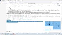
Yes, in that example the Zeners clip the signal. Your NAD is a bit different (forget the Zeners in the NAD for now) because it uses the two 1N4148 diodes to clip the signal but crucially it uses the resistor network to set a DC voltage on those diodes to 'lift' the operating point of them above the expected -/+0.6 volts they would otherwise clip at.
The Zeners appear to do a couple of things.
1/ They 'loose' us some voltage meaning the resistor network can use smaller low power resistors.
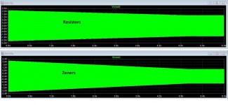
2/ They will modify the clipping in relation to supply voltage. When the supply dips under load the clipping point is lowered... neat eh 🙂
Try it. Make the supplies 25 volt and the input 4 volts and compare the clip level to the -/+37 volt supply.
The Zeners appear to do a couple of things.
1/ They 'loose' us some voltage meaning the resistor network can use smaller low power resistors.
2/ They will modify the clipping in relation to supply voltage. When the supply dips under load the clipping point is lowered... neat eh 🙂
Try it. Make the supplies 25 volt and the input 4 volts and compare the clip level to the -/+37 volt supply.
You could but I think that also might alter the way the circuit takes into account supply variation under load.
You see NAD use a relatively small power supply that can not maintain a high power delivery but it will hold up under transients. So you get an amp that can deliver real world music at high level and without clipping, but if tested under sine wave conditions has a much more modest output because the supply voltage is pulled down. That is down to commercial decisions and using small transformers and heatsinks and so on.
So the soft clip function isn't just fixed at a predetermined level, it has the ability to be altered by the supply voltage. Fixed resistors would still allow that up to a point but the Zener value is chosen so that it essentially drops out of conduction when the supply falls far enough, and so that gives a different 'curve' to the soft clip thresholds.
That could be tested in the simulation... one for another day 🙂

You could but I think that also might alter the way the circuit takes into account supply variation under load.
You see NAD use a relatively small power supply that can not maintain a high power delivery but it will hold up under transients. So you get an amp that can deliver real world music at high level and without clipping, but if tested under sine wave conditions has a much more modest output because the supply voltage is pulled down. That is down to commercial decisions and using small transformers and heatsinks and so on.
So the soft clip function isn't just fixed at a predetermined level, it has the ability to be altered by the supply voltage. Fixed resistors would still allow that up to a point but the Zener value is chosen so that it essentially drops out of conduction when the supply falls far enough, and so that gives a different 'curve' to the soft clip thresholds.
That could be tested in the simulation... one for another day 🙂
so could you improve this amp and its output quality, which is already very good
Do you mean to just improve the soft clipping action or improve the whole amplifier? The soft clipping action is only a means to reduce the nasty sound and speaker damaging effects of clipping which comes with the territory of smaller amps. As NAD obviously realise, modest power amplifiers like the 3130 will inevitably be overdriven when users start enjoying their favourite music and likely cranking up the volume.
Logically, you can't damp clipping effects without just introducing another distortion via that "soft clipping" circuit since it's really a crude form of dynamic compression. Sure, the resulting sound is much less harsh or damaging to your speakers than clipping and may go unnoticed on brief signal peaks but if you want to improve the already good sound quality, the obvious path in that case, is more power and thus no need for any form of compression.
Logically, you can't damp clipping effects without just introducing another distortion via that "soft clipping" circuit since it's really a crude form of dynamic compression. Sure, the resulting sound is much less harsh or damaging to your speakers than clipping and may go unnoticed on brief signal peaks but if you want to improve the already good sound quality, the obvious path in that case, is more power and thus no need for any form of compression.
so could you improve this amp and its output quality, which is already very good
Not really, not without changing a lot of things.
The basic circuit design of the amp contributes most to the perceived audio quality... its signature. Any 'improvements' would really come down to a larger power supply that does not sag under load but that would mean a much more expensive transformer, larger PSU caps and larger heatsinks with perhaps more expensive and robust output transistors.
So you could make the NAD into an amp whose performance held up on sustained testing and into 4 ohm loads, but it would cost three times as much and be larger and heavier but crucially when used in a normal domestic setting probably wouldn't be any different to listen to.
You would be surprised how loud even 3 or 4 watt output is into efficient speakers. Look at all those building the little ACA amp with its 6 or 7 watts output power. And it sounds fantastic.
I should correct my post above by not calling the clipping a form of dynamic compression either. Lets just leave it as Mooly describes and demonstrates the amplifier's dynamic behaviour as the power demands.
- Home
- Amplifiers
- Solid State
- nad 3130 Centre voltage adjustment issue