i checked this and it was fine, thankssuggest to check Q410, 2SD669 is suspected defective.
Back at the start you mentioned an offset of around 40 to 50 millivolts but now you say it is 256 millivolts.
That sounds like something has changed following the latest mishap. I'm wondering if you now have two issues rather than one.
With no speaker connected is the idle current still OK on the repaired channel? That is a pretty good check that the output and driver stage is OK.
The midpoint voltage is set by the preset altering the current in 'constant current source' Q402 and it does that by altering the reference voltage developed between the base of the transistor and the positive rail.
You could check and compare the voltages across D402 and D404 with the other channel. Also compare voltage across R436.
i also took some voltages of the below, and they seem a bit odd to me
Q412
B 1v
C 37.1v
E 0.4v
Q414
B 1.3v
C 37v
E 0.7v
Q411
B 0.6v
C 37.2v
E 1.2v
Q413
B 1.1v
C 37.3v
E 0.5v
Are the odd numbered one the other channel?
Q412 and 414 are the drivers and tbh the voltages look in the right ball park give or take. The PNP devices should be more lower in value than those on the NPN.
Plus 0.4v on the emitter of Q412 would imply a base voltage of around 1v which is what you have.
Q414 base is 0.6 volts lower than the emitter (which is correct for a PNP) but these should be lower, in other words negative 1.1 on the base and negative 0.5 on the emitter.
A good way to measure these is put your meter negative lead on the main audio output line (emitter of Q416 and Q418) and then measure forwards toward the front end.
(the problem measuring to all the points as you have done is that if the output point drifts (as it will) then all the results change as well and so by the time you take the final measurement they might all have moved by quite a bit)
So you should see +0.6 on the base of Q4136 and +1.2 on the base of Q412. Measure now to the base of Q418 and you should have negative 0.6v and then negative 1.2 on the base of Q414.
The difference between the base of the drivers is therefore about 2.4 volts and that is what is needed to turn all four on and for your bias current to flow.
a little(very little bit of progress
it appears the soft clipping has an influence and the voltage drops at the speaker terminals to about 40mv and the pot has a little adjustment
i soldered the shorts back out and turned it on/tried it out, this is what i found
both channels sound perfect without soft clipping enabled, but the faulty one is very distorted with it on
also with soft clipping on or off, when you increase the volume to say half, the current must be realy elevating as the bulb starts to light up, so clearly something still a miss, but ive been at it since 8am this morning and im beat(tired) not beaten 🙂 so time to call it a day with this one.
I'll have a think later 🙂 I assume that the switch SW10 is the soft clip.
Just thinking aloud... if so then that should not be able to influence DC conditions unless C414 was faulty... which could remove as a test.
Just thinking aloud... if so then that should not be able to influence DC conditions unless C414 was faulty... which could remove as a test.
That is exactly what is expected. It takes ten times as much power each time the volume is doubled. You can't run the amp normally with a light bulb in series, the point of the light bulb is for diagnostics to prevent catastrophic currents when you have a fault.also with soft clipping on or off, when you increase the volume to say half, the current must be realy elevating as the bulb starts to light up, so clearly something still a miss, but ive been at it since 8am this morning and im beat(tired) not beaten 🙂 so time to call it a day with this one.
must admit i didnt want to try it without just yet untill i have found why i cant get the voltages down.
SW10 is the soft clipping, and D411 is not installed, not even a space on the board for it.
SW10 is the soft clipping, and D411 is not installed, not even a space on the board for it.
funny enough ive had going through my head all day about changing the electroliticsI'll have a think later 🙂 I assume that the switch SW10 is the soft clip.
Just thinking aloud... if so then that should not be able to influence DC conditions unless C414 was faulty... which could remove as a test.
maybe i should trust my own judgement sometimes.
Removing C414 would remove any possibility it was causing an issue but before you do John mentioned the bulb...
I never though of the bulb tbh while you were measuring voltages and it could be important actually because the bulb will reduce supply voltages a little and that could cause the adjustment range to be out of tolerance. If you are happy with the amp apart from the small DC offset then it might be worth trying on full mains and seeing if the offset is different.
I never though of the bulb tbh while you were measuring voltages and it could be important actually because the bulb will reduce supply voltages a little and that could cause the adjustment range to be out of tolerance. If you are happy with the amp apart from the small DC offset then it might be worth trying on full mains and seeing if the offset is different.
i wasnt sure about the bulb tester, i had an idea it might affect in some way, but i get a full 235+v primary with the bulb tester connected and i guess there is a tolerence on these transformers, but proberbly not as much as today where things are designed for 220v+
i will change the capacitor later, i might even do a few of the others as i have loads of them and this amp had a bit of damp damage when i brought it and a few of the caps looked a bit corroded.
i let you know how i get on later this afternoon.🙂
i will change the capacitor later, i might even do a few of the others as i have loads of them and this amp had a bit of damp damage when i brought it and a few of the caps looked a bit corroded.
i let you know how i get on later this afternoon.🙂
The Nad is unusual because it uses a single ended rather than a differential input stage. That means the input transistor has to be biased to a definite value to get the output DC offset to zero and the problem with that is the circuit being sensitive to supply changes and temperature changes.
Any damp that is causing conductive paths around Q404 could cause problems. Everywhere else is really to low impedance for slight leakage to effect things.
Any damp that is causing conductive paths around Q404 could cause problems. Everywhere else is really to low impedance for slight leakage to effect things.
no difference without bulb tester and i have changed that cap on both channelsi wasnt sure about the bulb tester, i had an idea it might affect in some way, but i get a full 235+v primary with the bulb tester connected and i guess there is a tolerence on these transformers, but proberbly not as much as today where things are designed for 220v+
i will change the capacitor later, i might even do a few of the others as i have loads of them and this amp had a bit of damp damage when i brought it and a few of the caps looked a bit corroded.
i let you know how i get on later this afternoon.🙂
The Nad is unusual because it uses a single ended rather than a differential input stage. That means the input transistor has to be biased to a definite value to get the output DC offset to zero and the problem with that is the circuit being sensitive to supply changes and temperature changes.
Any damp that is causing conductive paths around Q404 could cause problems. Everywhere else is really to low impedance for slight leakage to effect things.
so a little bit of progress
ive learnt alot in life not to trust used spare parts and the spare pot i fitted turns out to be as bad as the first one
so.. now the voltages on both channels are stable -both centre voltages are quite close to 0v
idle voltages are a bit apart, close to +20mv on one channel but +40mv on the other, but these you could prob live with? other wise its changing resistor time as this amp has no pot adjustment for the idle.
the problem is the left channel just does not like the soft clipping switch on, and it is proper distorted
this is all with the solders re shorted and no bulb tester.
although the transistors tested out ok could one of them still be the cause or is this unlikley?
ive tested all the components that go to ground and these all seem ok.
got other stuff to do today so ill have another look tomorrow eve if anyone comes up with suggestions😕
a little suggestion,
its been on post #2
measuring the R408,410,412,414,416,418,420 and 436, Also diodes 402 and 404.
this time measure them not by ref to ground,
but compare the two channels by measuring voltages across each resistor, diode...
find out which one has the different value by comparing with the good channel.
and we make them equal...
Sounds like progress 🙂
If the amp sounds OK without the soft clip on then I can't see it being a transistor.
I'll think on that one as well...
If the amp sounds OK without the soft clip on then I can't see it being a transistor.
I'll think on that one as well...
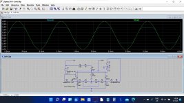
Try this and use it to look at voltages and try and figure out where yours is going wrong.
This is the soft clip from the NAD. It works by clipping the input signal and it does so by setting a DC voltage on the two IN4148 diodes. When the signal exceeds those voltages plus the diode volt drop it is clipped by shunting it to ground.
So you can see the soft clip is really a passive circuit that does not need the amp at all (although it needs the supply voltages to provide the DC reference points).
Attachments
are some of the resistors purposly the wrong way round?
shouldnt the current values be the same on C3 and C4
and shouldnt the output voltage be the same as the input but clipped?
shouldnt the current values be the same on C3 and C4
and shouldnt the output voltage be the same as the input but clipped?
Last edited:
Try this and use it to look at voltages and try and figure out where yours is going wrong.
This is the soft clip from the NAD. It works by clipping the input signal and it does so by setting a DC voltage on the two IN4148 diodes. When the signal exceeds those voltages plus the diode volt drop it is clipped by shunting it to ground.
So you can see the soft clip is really a passive circuit that does not need the amp at all (although it needs the supply voltages to provide the DC reference points).
why would the voltage be lower when clipped? ,wouldnt this reduce the volume?
Attachments
- Home
- Amplifiers
- Solid State
- nad 3130 Centre voltage adjustment issue