Bob,
That sounds like the best.
Another alternative to the CD mica caps. I have used Miconics mica caps from PCX before and they were fine. I don't know if there is a source for these or other mica caps in Europe, but it would be worth looking.
That sounds like the best.
Also I have a quite specific question - the c34 27pf Mica caps are not available from Mouser for ages -(5982-08-100V27-F Mica Capacitors 27pf 100V 0805 5%)- and only via the US special postage (£) from Farnell, does any one have a suitable alternative till these are back in stock??
Another alternative to the CD mica caps. I have used Miconics mica caps from PCX before and they were fine. I don't know if there is a source for these or other mica caps in Europe, but it would be worth looking.
Also I have a quite specific question - the c34 27pf Mica caps are not available from Mouser for ages -(5982-08-100V27-F Mica Capacitors 27pf 100V 0805 5%)- and only via the US special postage (£) from Farnell, does any one have a suitable alternative till these are back in stock??
Just a note to present /future builders.... did you noticed that on Google BOM rows goes from I to P?
There are hidden rows with RS Components, Distrelec and Digikey codes.
RS used to have them but it seem the code in BOM is no longer valid... but Digikey has stock of them.
BTW you can use C0G/NPO caps as suggested by Andrew with confidence, you can find codes for them on the On a Budget BOM.
Micas sound a bit better but C0G/NPOs are really good too, particularly in C34 there's no a big difference.
explorer is made with brown paste
.....gggrrrraaaaaAAAGGHH.... dagggnamit!
Thank you Dario for Ponting that out....(and you other guys for alternative suggestions) I'd been cross referencing everything at work. This forced me to look at the BOM in Windows Explorer on my nice work PC.
CONSIDERABLY more can be seen on my Chrome browser on this darn phone! !
Wil go with C0G . Looked at x2y caps - technicaly brilliant , but you can't take advantage of both earths at C34 without bodging the board.... (may explore later and report especially at input LP filter)
http://www.johansondielectrics.com/surface-mount-products/x2yr-filter-a-decoupling-capacitors.html
Last edited:
Finished building the 2 modules, 1 is good, the other wel.... 🙁
The relay kicked in and then 2 seconds later a big bang and a little spark. Immediately turned it off and inspected the board.
The 3886 is stuffed, pins look burnt. It almost looks like 2 pins have been soldered together. I could not tell you whether that was due to the spark or not.
Am about to order another chip from mouser, however i may hold off until someone can give me some pointers. The last thing i want to do is put a new chip in and see it go bang again.
The 3886 is stuffed, pins look burnt. It almost looks like 2 pins have been soldered together. I could not tell you whether that was due to the spark or not.
Post some pics of the bad build


So here are some photos (apologies for the quality)
Apart an excess of solder I can't see major problems like solder bridges....
Desolder the LM3886 and power the module and then measure voltages.
Not sure which points you would like me to check.
The only one i was game to check was between out and outgnd which had 3.6v.
The only one i was game to check was between out and outgnd which had 3.6v.
Not sure which points you would like me to check.
The only one i was game to check was between out and outgnd which had 3.6v.
Look at the bottom of the board, there are marked testing points for +-14.6 V, +-35V (reference to nearest ground) and 1.25 (measure between resistors' pins)
Hi Everyone
Searching through the 100+ pages. I found i a set of test points that Dario gave to Voxxonline.
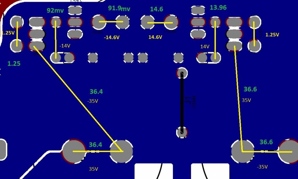
Does this suggest that IC101 is dodgy.
Will the 1.4v difference where 35v should be make a difference?
Searching through the 100+ pages. I found i a set of test points that Dario gave to Voxxonline.

Does this suggest that IC101 is dodgy.
Will the 1.4v difference where 35v should be make a difference?
Last edited:
the +-36 Vdc will not affect operation. It is below the 84V maximum (when signal is applied).
The ~90mVdc is the indication of a serious problem.
The ~90mVdc is the indication of a serious problem.
the +-36 Vdc will not affect operation. It is below the 84V maximum (when signal is applied).
The ~90mVdc is the indication of a serious problem.
Unfortunately i have to agree 🙁
Searching through the 100+ pages. I found i a set of test points that Dario gave to Voxxonline.
Does this suggest that IC101 is dodgy.
First desolder the LM3886, repeat measure.
If values don't change, desolder the LM318, repeat measure.
If values don't change remove T201 and measure D205, if it's not -14V replace both with new parts.
Now measure again, you should have correct values.
From there double check every joint for bridges to other pins or ground plane.
Measure resistors and caps on PS and signal paths, since there are no active parts mounted you should be able to measure most of them on board.
If all seem right solder a new LM318 and a new LM3886, take care to not use too much solder, your joints are too rich.
Cross your fingers and power on.
It could be a good idea to use a Dim-bulb Radio Tester for the first power up.
Will the 1.4v difference where 35v should be make a difference?
No
Last edited:
....... take care to not use too much solder, your joints are too rich.
Cross your fingers and power on.
It could be a good idea to use a Dim-bulb Radio Tester for the first power up.
I hesitated to comment because you can't get better help than what Dario is offering. I just want to reinforce the need for great care in inspecting for tolerances. I recently discovered a long standing problem on another amp was due to a mounting screw with a wide head just barely touching the bare copper on a negative power rail pad. It was found only when the amp was tested with that PCB floating - away from the chassis. I had cleaned and reflowed the solder on that board at least six or seven times.
So please make full use of good light and a magnifying lens as you reassemble. A short or bridge can easily hide in plain sight.🙄
Also curious about what size solder and tip you are using. I believe Dario has some recommendations for that in the build guide.
Good Luck!
Attachments
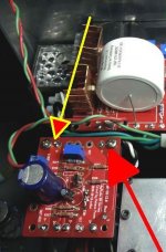
Alright so what i have is this
1. LM3886 was already removed so went straight to removing LM318. Measured around 120mv.
2. Removed T201 and measured D205. Measurement = 14.6v
Other side = 13.9v
1. LM3886 was already removed so went straight to removing LM318. Measured around 120mv.
2. Removed T201 and measured D205. Measurement = 14.6v
Other side = 13.9v
Thanks Dario, that helped alot.
As long as 14.6v is acceptable i just need to replace T201, LM318 and 3886. Do you think i should replace D205?
Bob I can assure you i will do my best to keep everything clean. 🙂
As for the solder, the thickness was around 1mm. The tip was a pretty thin one i couldnt tell you what exactly.
I now have some cardas solder which is .81mm. However the original soldering up was done with the 1mm duratech from the local electrical shop.
I will post some pics soon, cases had arrived Friday. Decided to go a dual case route, with the dac in its own case and the amps with the tortuga in the other.
This is the link to the case.
Wholesale Product Snapshot Product name is Full aluminum Power amplifier chassis/amplifier case Enclosure
Ryan
Thanks Dario, that helped alot.
You're welcome 🙂
As long as 14.6v is acceptable i just need to replace T201, LM318 and 3886. Do you think i should replace D205?
It should not be necessary.
But if have to pay a significant amount of shipping fees to source parts maybe it would be convenient to buy also the zener and the LM317 too.
which transformer to choose?
Hello,
I plan to order a custom made toroidal transformer for the MyRef FE that I am currently assembling. I think of 400 VA 4x25 V secondaries for a stereo. But now I'm in doubt what is the best option. Could it be better to have two 160VA (or even 200VA) 2x25 V secondaries transformers and go dual mono? The price is similar for two 160VA or one 400 VA transformer.
Any suggestions are welcome
400VA is rather big for a two channel chipamp.
The Myref has a maximum output of 50W to 55W.
The total for two channels is 100W to 110W.
Using the usual recommendations you will find good performance from a transformer of 110VA to 220VA.
There are some who say that 300VA (for two channels) is an optimum for their builds.
I can't recall anyone specifying 400VA.
- Home
- Amplifiers
- Chip Amps
- My_Ref Fremen Edition - Build thread and tutorial