What pre? I am building a lighter note for this project.....if it ever gets here. It should be complete by the time these boards are printed.....hopefully.
I suppose I shouldn't say pre-amp since I was/am using a light speed.
Passive pre perhaps?...
Squalor, I hope you find the problem soon...
Bill
Hi Dario,
I am interested in joining the GB.
First partecipant from India:
- ClaveFremen x 2 (IT)
- Suburra (IT)
- SoIL4x4 (US)
- Bmcbob (US)
- Randytsuch (US)
- alex70ita (IT)
- b.veneri (IT)
- StefanoSan73 (IT)
- diymax62 (IT)
- billo44 (UK/JP?)
- TjongKristian (ID)
- arthur x 2 (N/A)
- PMeade (US)
- Badrisuper (IN)
- ?
- ?
- ?
- ?
Last edited:
Hi Joseph,
let sum:
You measured:
The first thing to do, IMHO is to fix rails voltage.
So reflow the big smoothing caps and diodes connection to ground and measure again.
Probably LM318s and LM3886 are gone so, if I were in your shoes, I'll remove both.
To remove the LM318 easily I suggest you to buy the ChipQuik desoldering alloy (Mouser 910-SMD1) along with new LM318s and LM3886s.
To remove the LM3886 cut all pins and then remove all pins one by one.
With opamps removed you can measure again being sure that a broken chip don't affects your measurementes.
If all PS measures will be fine you can, then, solder the new chips and, hopefully, have working amps.
let sum:
You measured:
- ca 26V on secondaries. (good)
- ca 14.5 on reg's output (good)
- ca 19V on smootihng caps (BAD)
The first thing to do, IMHO is to fix rails voltage.
So reflow the big smoothing caps and diodes connection to ground and measure again.
Probably LM318s and LM3886 are gone so, if I were in your shoes, I'll remove both.
To remove the LM318 easily I suggest you to buy the ChipQuik desoldering alloy (Mouser 910-SMD1) along with new LM318s and LM3886s.
To remove the LM3886 cut all pins and then remove all pins one by one.
With opamps removed you can measure again being sure that a broken chip don't affects your measurementes.
If all PS measures will be fine you can, then, solder the new chips and, hopefully, have working amps.
Attachments
Dario, I truly appreciate the help your giving me. Thank you, sir.
I will not be able to get much done until the 21, big music festival in town means lots of work hours for me. If I must make another Mouser order, maybe I can get some extra things. I believe behind every problem is an opportunity. Maybe I can get some Caddock to replace the 68R and get some Susumu in place of the PRP I have now. If it only adds a few dollars to the order, why not ?
I will not be able to get much done until the 21, big music festival in town means lots of work hours for me. If I must make another Mouser order, maybe I can get some extra things. I believe behind every problem is an opportunity. Maybe I can get some Caddock to replace the 68R and get some Susumu in place of the PRP I have now. If it only adds a few dollars to the order, why not ?
Just finished a little experiment with C102/202. I played a live Oscar Peterson piece that exhibited that raggedness in the piano crescendos I mentioned earlier. I was thinking of the "smoothing" role of those pieces so I put them back in. I lost a bit of the clarity/airiness and the distortion/fuzz was still there. That makes me think the FEs can do quite well without those caps. The effect can be reduced by lowering the volume but it happens at the same spot on the pot in either case.
BTW, Now have Caddocks in R104/204 and R13. I haven't heard a lot of change there. I will reverse the parts after a little more listening. Going for C7 and C30 next.
BTW, Now have Caddocks in R104/204 and R13. I haven't heard a lot of change there. I will reverse the parts after a little more listening. Going for C7 and C30 next.
Just something general like this I believe. Iv'e used them on the Mini DAC.
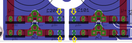
Gets a little tricky, but you can also check for continuity through the board on all the leads you can reach by placing the board verticle in a small vice or use masking tape.
I have found a solder bridge under some small caps from excess solder that flowed up the leads and caused a short that was hidden. Also check for solder bridges around the SDM parts.
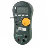
That's what I did when I lost the working channel, Heatsink on the table, boards up to measure. Wonder if my 3886 has a cold joint ? I don't completely understand my DMM. It has two V settings. One is V~ 200 & 300 and one V --- with a line above the dashes. I think the continuity setting looks like a diode symbol ->l so which one should I use ? Which setting should I use for DC offset ?
Do you have a Susumu at R12 ? Do you just solder legs onto it to convert it from SMD to thru-hole ?
I did not realize the board could be powered up without 3886 and 318.
V~ is AC and the other is DC. Everything before the power enters the PCB is AC - after is DC. Continuity looks like a horn bell or a speaker and should beep when you touch the probes together. Can you post the brand and/or model number of your DMM?
There are no SDM parts on the top side of my build. I'm using sockets throughout the beta process. I believe Dario is going to add some SDM options but I suspect they will also be on the underside.
There are no SDM parts on the top side of my build. I'm using sockets throughout the beta process. I believe Dario is going to add some SDM options but I suspect they will also be on the underside.
Last edited:
I have a Ryobi but it is functionally identical to yours. The three with arrows are all I use 90% of the time. There should be an auto-range option that takes care of the values without the need for user selection. The select button should cycle through the options for each item on a position of the yellow dial by showing the matching icon in the window.
Attachments
Last edited:
Dario, I truly appreciate the help your giving me. Thank you, sir.
You're welcome. 🙂
I will not be able to get much done until the 21, big music festival in town means lots of work hours for me. If I must make another Mouser order, maybe I can get some extra things. I believe behind every problem is an opportunity.
It reminds me a thing... a little OT that probably only Bob can understand...
When I was young I've modded my Amiga 2000 with a double speed MC68000.
At first it worked and then I've, by mistake, connected +12V to ground... result:
I've fried the Agnus chip... do you know what was the first thing I said?
Well.. the second, I can't write the first thing... 😀
Well... I'll buy the Fat Agnus then...
(the Fat Agnus was the upgraded chip)
Maybe I can get some Caddock to replace the 68R and get some Susumu in place of the PRP I have now. If it only adds a few dollars to the order, why not ?
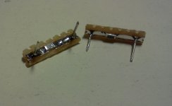
You can't mount permanently the Susumus on the beta boards, to test them I've used an home made adapter.
There are very good sounding TH alternatives, like Rikens.
Just finished a little experiment with C102/202. I played a live Oscar Peterson piece that exhibited that raggedness in the piano crescendos I mentioned earlier. I was thinking of the "smoothing" role of those pieces so I put them back in. I lost a bit of the clarity/airiness and the distortion/fuzz was still there. That makes me think the FEs can do quite well without those caps.
Since I've fried one of my LM318s in the FEs I'm using the TP board in this moment.
That raggedness is present also on those.
Maybe is related to LM318... or maybe the nickel under the gold plating of PCBs.
Can you hear it on Siva's modules (without the LF01s)?
BTW, Now have Caddocks in R104/204 and R13. I haven't heard a lot of change there. I will reverse the parts after a little more listening.
Strange, in straight direction they sound colored, in the opposite they're more neutral but a bit edgy.
You're comparing them with KOAs or what?
Going for C7 and C30 next.
I can't wait... 😀
I'll try the V1.3s and report back. If the raggedness is still present, then it might be correct to assume it's not a response by the amps but too high a ceiling in the recording process and is mainly program dependent. I just started with the new Caddocks but will try "swapping and twirling" in the next day or so.
What I did notice was some browning on the leads of the C102/202 caps at the spot where they touch those homemade sockets I installed. That indicates an incomplete contact or intermittent loss of continuity to me. There is probably less of that with the real sockets, but that prompts me to think there may be some small change - hopefully improvements - when all components are solid soldered to the final boards.
What I did notice was some browning on the leads of the C102/202 caps at the spot where they touch those homemade sockets I installed. That indicates an incomplete contact or intermittent loss of continuity to me. There is probably less of that with the real sockets, but that prompts me to think there may be some small change - hopefully improvements - when all components are solid soldered to the final boards.
I'm sure everybody knows this but just to be double clear...V~ Everything before the power enters the PCB is AC - after is DC.
After the diode bride voltage is DC.
I went and refreshed my understanding of bridge rectification here.
Rectifier circuits : DIODES AND RECTIFIERS
I hope I'm not being too pedantic I know this is real basic stuff, but it helps me to go over the basics.... electronics is still all mystery and magic to me 🙂
Not at all Bill, I realized that mistake as I started a little afternoon nap, but was too lazy to correct myself. That's a very important safety tip as well.
Thanks for your eagle eye and the correction.
Thanks for your eagle eye and the correction.
Last edited:
I'll try the V1.3s and report back. If the raggedness is still present, then it might be correct to assume it's not a response by the amps but too high a ceiling in the recording process and is mainly program dependent.
Thanks Bob.
It's possible, nevertheless when my FEs will be repaired (hopefully tomorrow) I'll check if some of the components can give that effect.
I just started with the new Caddocks but will try "swapping and twirling" in the next day or so.
Fine 🙂
What I did notice was some browning on the leads of the C102/202 caps at the spot where they touch those homemade sockets I installed. That indicates an incomplete contact or intermittent loss of continuity to me. There is probably less of that with the real sockets
It's possible, with round sockets I can't see that.
that prompts me to think there may be some small change - hopefully improvements - when all components are solid soldered to the final boards.
You bet! 😉
Those sockects, while useful for testing, have a slight impact on sound.
In fact it's perfectly possible that they have a role in that raggedness.
I sprang a leak in a water cooled Athlon PC. The results were... dramatic....and expensive.by mistake, connected +12V to ground... result: I've fried the Agnus chip..
Sorry for your loss but this news makes me feel strangely better; I guess misery loves company.Since I've fried one of my LM318s in the FEs I'm using the TP board in this moment.
You can't mount permanently the Susumus on the beta boards, to test them I've used an home made adapter.Why ? silver
Me too . Thanx for the link.electronics is still all mystery and magic to me
Last edited:
Sorry for your loss but this news makes me feel strangely better; I guess misery loves company.
We all make errors... I wrecked several PCBs... fried three commercial receivers (an H/K, a NAD and a Marantz...)
It's part of the hobby 😉
Why ?
See the attachment, I'm not sure you can solder that thing... but you can try 😉
Attachments
Enough Lurking! I'm IN
Dario,
A slight confusion on my part. How are we counting an order here? You estimated the price as "per PCB pair". If I want a total of 4 PCBs or 2 pair PCBs, is that "x4" or "x2" in your list?
Anyway, please put me down for the 4 PCBs or 2 pair PCBs, your choice.
How close does that get us to the need 20?
Jac
A slight confusion on my part. How are we counting an order here? You estimated the price as "per PCB pair". If I want a total of 4 PCBs or 2 pair PCBs, is that "x4" or "x2" in your list?
Hi Jac,
I've made a bit of confusion with arthur's PCBs...4 PCBs translates in x2
US partecipants are reaching Italians 🙂 :
- ClaveFremen x 2 (IT)
- Suburra (IT)
- SoIL4x4 (US)
- Bmcbob (US)
- Randytsuch (US)
- alex70ita (IT)
- b.veneri (IT)
- StefanoSan73 (IT)
- diymax62 (IT)
- billo44 (UK/JP?)
- TjongKristian (ID)
- arthur x 2 (N/A)
- PMeade (US)
- Badrisuper (IN)
- lehmanhill x2 (US)
- ?
- ?
How close does that get us to the need 20?
Two partecipants more (or one x2) 😉
Last edited:
- Status
- Not open for further replies.
- Home
- Amplifiers
- Chip Amps
- My_Ref Fremen Edition - Beta build/Fine tuning