Its great to see more people join the list. I am excited to get this underway.
Me too. 🙂
Feedback is important to refine or confirm choices.
Dario even though this is a pre release run do you really expect to make any changes to the final run? When are you planning to have boards run?(not pushing just curious as to when I need to start ordering all the pieces and parts). Thanks again for doing this!
Until I finalize the PCB for ordering it could change a bit.
Nothing big but some components could change footprint.
BTW from money collecting start to order will pass (at least) a week and after the order 20-30 days will pass to have PCBs at my home and 10-15 days to have PCBs at your home.
There's plenty of time to order parts... 😉
But, maybe, you're referring to difference from this RC and RTM version?
If all goes well the RTM will be identical to the RC.
hi Clave, I would very much like to join the list. thanks.
please add 4 channel pcbs for me
Done:
- ClaveFremen x 2 (IT)
- Suburra (IT)
- SoIL4x4 (US)
- Bmcbob (US)
- Randytsuch (US)
- alex70ita (IT)
- b.veneri (IT)
- StefanoSan73 (IT)
- diymax62 (IT)
- billo44 (UK/JP?)
- TjongKristian (ID)
- arthur x 4 (N/A)
- ?
- ?
- ?
- ?
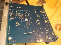
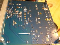
Here are pics of the solder side of the two FE boards.
With my Greenlee DM55 DMM set on V~200 one Antek measures 25.8 and the other 25.9 With the bulb tester inserted after the fuse 0V , turning the switch on the tester, still 0V. Oh well, I built it out of junk so that's what I ended up with.
Reason I wanted to re-flow is I soldered in three sessions. First, the SMD and 318. The joints were smooth and shiney. Next day, the resistors and small caps, same results. Daze later, the Harwin spades, C3, C8, C9, C13 and R3. I think I was at too low a temperature during this. Especially the Caddock, the legs seem to be of a different material and I had to stay extra long to get the solder from the leg to the pad. The Black Gate at C9 seemed to have a cold joint too. The panny HA joints were rough textured. I re-flowed one channel and powered up again.
I heard music ! Not pretty music, but it does function.
Attachments
Glad you're making progress! So you are getting the relay click and the LED light on that amp?
Heating some parts was difficult till I realized larger pins that connect to large ground surfaces suck up a lot of heat. I have often intended to ask if there was even something inherent in the construction of the large caps that influences heat absorption. One leg solders rapidly while the other on the same cap takes much longer. I've adjusted accordingly. Thanks for the photos but can you post some of the top side also?
Heating some parts was difficult till I realized larger pins that connect to large ground surfaces suck up a lot of heat. I have often intended to ask if there was even something inherent in the construction of the large caps that influences heat absorption. One leg solders rapidly while the other on the same cap takes much longer. I've adjusted accordingly. Thanks for the photos but can you post some of the top side also?
Last edited:
Reason I wanted to re-flow is I soldered in three sessions. (...) I heard music ! Not pretty music, but it does function.
OK Joseph, you're right, from pics some solder joints really need to be reflowed (big smoothing caps, C9 for sure)
Reflow all suspect joints and for this turn avoid semiconductors (opamps, transistors).
All pads connected to the ground plane needs to be solder with a pretty high temperature.
First warm some seconds the pad, then touch also the lead and apply solder.
Let us know how is doing.
Another partecipant from States:
- ClaveFremen x 2 (IT)
- Suburra (IT)
- SoIL4x4 (US)
- Bmcbob (US)
- Randytsuch (US)
- alex70ita (IT)
- b.veneri (IT)
- StefanoSan73 (IT)
- diymax62 (IT)
- billo44 (UK/JP?)
- TjongKristian (ID)
- arthur x 2 (N/A)
- PMeade (US)
- ?
- ?
- ?
- ?
- ?
Last edited:
In desperation I even bought one of these. You have to be extremely careful with the exhaust heat flow but it does the trick. Also, torch attachment is great for use with heat shrink tubing.
Mini Butane Gas-Powered Iron - RadioShack.com
Mini Butane Gas-Powered Iron - RadioShack.com
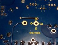
I have often intended to ask if there was even something inherent in the construction of the large caps that influences heat absorption. One leg solders rapidly while the other on the same cap takes much longer. I've adjusted accordingly.
It's normal, one pad is alone, the other is connected to PGND's ground plane via too large thermals (in RC boards I've reduced thermals traces widht so it should be less an issue).
I've reported that problem in one of the first posts... 😉
The ground plane connections are more difficult to solder, thermals width too large (it will be fixed in the final boards). Use a higher soldering temperature on those.
Joseph, reflow also the solder pad of LM3886 ground.
Attachments
Last edited:
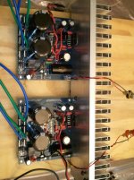
Here is a pic of the top. This will teach me not to make fun of Dario's heatsink. My sink has been beat with the ugly stick too.
I just made new Fast-on to RCA leads using solid copper/teflon wire (apex jr) and new parts. The Right channel cleaned up, the Left channel only a click. I then re-flowed everything that looked suspect on the Left, still just a turn-on click.
The (left) side that is not working, there is a small dent in the top of C8, the Pannasonic TS-HA smoothing cap. I wonder ?
Attachments
The Right channel cleaned up, the Left channel only a click. I then re-flowed everything that looked suspect on the Left, still just a turn-on click.
Fine so you have one working channel (sort of) and one that just clicks (it's the relay, isn't it?)
So on both you don't have DC at output, good.
Probably the LM318 is gone but before saying so it's better to measure rails and regulator output (and 1R resistor too).
See attachment for reference.
The (left) side that is not working, there is a small dent in the top of C8, the Pannasonic TS-HA smoothing cap. I wonder ?
I don't think so...
Attachments

Its great to see more people join the list. I am excited to get this underway.
Good to be on board, and good to see more people on the list already.
I will be looking to build a pair, probably use my current MyRef RevC ultimate transformers and pre-amp to start with.
Bill
C102,C202 14.39 14.45 14.38 14.39
C3,C8 19.24 0(cap by jumper) On the other board the meter is jumpy
Now both boards are dead
C3,C8 19.24 0(cap by jumper) On the other board the meter is jumpy
Now both boards are dead
Good to be on board, and good to see more people on the list already.
I will be looking to build a pair, probably use my current MyRef RevC ultimate transformers and pre-amp to start with.
Bill
What pre? I am building a lighter note for this project.....if it ever gets here. It should be complete by the time these boards are printed.....hopefully.
squalor, did you do the tests as described in post #457?
Yes, 25.8 and 25.9
Good, Dario will have to give you some more points to measure. Did you buy any LEDs for the build. I didn't see them in the photos.
No LEDs . If I went to RadioShack which ones should I buy. Do I need resistors for them ?
I still think this has something to do with my poor soldering skills.
I still think this has something to do with my poor soldering skills.
Just something general like this I believe. Iv'e used them on the Mini DAC.
Gets a little tricky, but you can also check for continuity through the board on all the leads you can reach by placing the board virticle in a small vice or use masking tape.
I have found a solder bridge under some small caps from excess solder that flowed up the leads and caused a short that was hidden. Also check for solder bridges around the SDM parts.
Last edited:
- Status
- Not open for further replies.
- Home
- Amplifiers
- Chip Amps
- My_Ref Fremen Edition - Beta build/Fine tuning