I would like a spot in the group buy for boards.
Done, so far:
- ClaveFremen
- Suburra
- SoIL4x4
- Bmcbob
- Randytsuch
- ?
- ?
- ?
- ?
- ?
- ?
- ?
- ?
- ?
- ?
- ?
- ?
- ?
- ?
- ?
I also wonder if you would get a better response if you started a thread in the group buy forum?
I choose to ask in this thread because I know a lot of people is following it and since these are the final testing boards.
But, maybe, I should reconsider. We will see... 😉
So far:
- ClaveFremen x 2
- Suburra
- SoIL4x4
- Bmcbob
- Randytsuch
- Alessandro Asborno (T-Forum)
- ?
- ?
- ?
- ?
- ?
- ?
- ?
- ?
- ?
- ?
- ?
- ?
- ?
Alessandro's DIY Audio Nickname added in place of complete name.
- ClaveFremen x 2
- Suburra
- SoIL4x4
- Bmcbob
- Randytsuch
- alex70ita
- ?
- ?
- ?
- ?
- ?
- ?
- ?
- ?
- ?
- ?
- ?
- ?
- ?
A second T-Forum member joined (DIYAudio nickname used):
Where's the rest of the world? 😀
- ClaveFremen x 2 (IT)
- Suburra (IT)
- SoIL4x4 (US)
- Bmcbob (US)
- Randytsuch (US)
- alex70ita (IT)
- b.veneri (IT)
- ?
- ?
- ?
- ?
- ?
- ?
- ?
- ?
- ?
- ?
- ?
- ?
Where's the rest of the world? 😀
At the risk of sounding like a two person conspiracy, it's hard to tell who is watching which threads. For those sitting on the fence, this dialog may be helpful and informative.
Regards,
RMM - Vice Chairman, FE Promotions 🙄
Regards,
RMM - Vice Chairman, FE Promotions 🙄
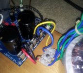
Hey Bob, Dario, I need some advice. I'm hooking up a pair of Antek AS2224 to the FE. http://www.antekinc.com/pdf/AS-2224.pdf
I have placed connectors on the Blue and Green secondary wires. The PDF does not indicate which is + and - but the tag on the side of the trafo has a dot by the Blue. Should I assume the Blue is + ?
On the AC side is two Red and two Black. Can I assume Red is hot and black is neutral ? Should I hook only one pair to mains (the other Red,Black unused) ? Should the Purple (shield) wire go to Earth (Chassis ground) ?
Blue = AC1 Green = Nac1
Last edited:
Last weekend a friend came to my place with his speakers Spendor SA1 to see my new amplifier (MyREF) and to see how Spendor sounds in my system. My speakers are System Fidelity 5010.
Before connecting Spendors i must say my friend was astonished how MyRef sounds and how precise is the soundstage (he is owning a Yaqin m10).
Sound of MyRef combined with Spendors was weak in bass, lifeless almost boring. I suppose this si because of their low sensitivity 85db compared to mine 90db.
Next moves are retrofitting shunt regulators and some higher grade lytics and resistors.
LE. posted in the wrong thread. Scusi Dario !
Last edited:
I have placed connectors on the Blue and Green secondary wires. The PDF does not indicate which is + and - but the tag on the side of the trafo has a dot by the Blue. Should I assume the Blue is + ?
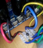
There's no + and -, we're talking about AC. 😉
The dotted wire is Hot/Phase, the other Neutral.
So Blue is AC and green NAC.
Pay attention to keep together the blue/green couples (one couple to AC1/NAC1, the other to AC2/NAC2).
If you need to identify couples you can use continuity check function of a multimeter, members of the same couple will have continuity.
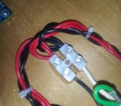
On the AC side is two Red and two Black. Can I assume Red is hot and black is neutral ? Should I hook only one pair to mains (the other Red,Black unused) ?
Yes but you should wire then in parallel (for 110V operation like in USA): red with red and black with black
Should the Purple (shield) wire go to Earth (Chassis ground) ?
Yes
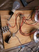
I didn't change the short leads from the ApexJr toroids yet - need more fastons - but this is how I did my dual Anteks. You should be able to follow the paths. In my service box black is hot and white is common/return - 2nd pic from left.
Attachments

Last edited:
At the risk of sounding like a two person conspiracy, it's hard to tell who is watching which threads. For those sitting on the fence, this dialog may be helpful and informative.
Regards,
RMM - Vice Chairman, FE Promotions 🙄
Mcbob, I think post #22 of that thread truly highlights your skills as a salesman. Great job😀
Well Mr. SolIl4x4, here I go again. 😀 The Audyn True Copper caps in C13 are simply stunning. The improvements in the width and 3D sensation of the stage brought a big wide smile to my face. These are the most expensive parts on the board, but at first audition, are a significant boost for those who have been bitten by the Audiophile bug. There seem to be many more qualities to report, but I'm running a couple passes of the IsoTek process before I dig in.
To Tom E. for digging hard for top choice components -
.....more to come !
To Tom E. for digging hard for top choice components -
.....more to come !
Last edited:
There seem to be many more qualities to report, but I'm running a couple passes of the IsoTek process before I dig in.
I'm curious to see if you'll find, as I did, that they sound better when new... 😀
Which orientation are you using?
My favourite is the opposite of the Zn (markings as in PCB)


Squalor, Your fuse should be on the hot side - is that what you have. I don't see a dim bulb tester. I don't power any new build without one. It is worth a trip to the local hardware.
Here is a simple one. Just put a socket in series on the hot leg. The switch on the socket isn't necessary - just what I had on hand.

Here is a simple one. Just put a socket in series on the hot leg. The switch on the socket isn't necessary - just what I had on hand.
Last edited:
Like this ? Should I turn it on ?
Isn't phase reversed on that line filter?
Usually brown is hot and blue neutral.
BTW whatever phase is it should work, power on with speakers not connected.
If both relay clicks than measure DC offset, it should be less than 20mV (mines are 14mV).
Then power off, connect your speakers and, hopefully, enjoy music. 😉
Or you can use a light bulb tester (ask Andrew or Bob, I never used one) to be absolutely safe.
Too early to tell on that change. Here's the orientation.
Fine, the opposite of the one I'm using. 😉
Try also the other one when you can.
Dario, brown and blue are European standards - I believe. U.S is B/W, Green for ground
Yes but on that filter I see two wires, one blue and one brown... 😉
And, If I see correctly orientation that wires are brown on phase/hot/live and blue on neutral
Last edited:
These reflect the process I used to insure correctness in the integrated build.
http://www.diyaudio.com/forums/chip-amps/203666-myref-integrated-solutions-8.html#post2883134
http://www.diyaudio.com/forums/chip-amps/203666-myref-integrated-solutions-8.html#post2883941
http://www.diyaudio.com/forums/chip-amps/203666-myref-integrated-solutions-10.html#post2885332
I now go so far as to resolder the colors/wires on the inlet module if they don't match.
Last edited:
Maybe this pic is better. Sorry to be sweating this so much but I killed my Kookaburra by hooking up a transformer wrong.
The blue wire of my IEC corresponds to the (left) longer prong, the brown lines up with the shorter prong (right).
I now have a bulb tester inserted after the fuse, a 3 amp Slo-blo.
Please jog my memory, what is the bulb supose to do ?
My test speakers are junky; I don't care if I lose them but yes. I will test DC offset. DMM set on 200mV to read correctly ?
Hit the switch ?
Attachments
- Status
- Not open for further replies.
- Home
- Amplifiers
- Chip Amps
- My_Ref Fremen Edition - Beta build/Fine tuning