At 10 Hz, I really cannot say. My Agilent 89410A/411A has outrageous 1/f in that
range; I even tried cross FFT via two channels, that seemed overly optimistic.
I don't know where the noise comes from, therefore the experiment with the
LTC2500-32. With it, I have clock phase noise etc under control. Some people claimed
that channels 1 and 2 of their 89410A were vastly different, I cannot say that
from mine.
For the measurements this evening, I put the lid on the box but did not use the
screws; I first must find 100U caps that are 0.5mm lower. But moving air from me
working at the table can probably be excluded.
I did not do anything to balance the transistors, any emitter resistor is too much
at this level. For FETs it's hopeless because of the lower gm. But then, even for
FETs, imbalance means only that you don't get the full advantage, maybe an
input C penalty, but it is not like that one mushroom will spoil the whole pot.
The Zetex spice models seem also to be optimistic modeling 1/f.
I got that amplifier working just today, so it is probably premature to
draw final conclusions.
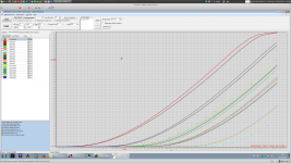
Art Of Electronics III has plots of Vbe for the Zetexes; I include the relevant
pages. They cannot replace the book, so I hope Winfield will forgive me
when I meet him on usenet sci.electronics.design.
One cannot survive without this book anyway.
Oh, regarding fluctuations, short the input and connect a scope on DC at the output. For 60dB gain I see up to +/- 1V random (in time and amplitude) output voltage fluctuations, even when mounted in a hermetically closed 10mm thick enclosure.
Oh, regarding fluctuations, short the input and connect a scope on DC at the output. For 60dB gain I see up to +/- 1V random (in time and amplitude) output voltage fluctuations, even when mounted in a hermetically closed 10mm thick enclosure.
That sounds much like popcorn noise. (pun alert!) It used to happen when
the process was poisoned by heavy metal ions. It does not seem to be
much of a problem nowadays.
There is an avalanching effect in the channel when Vds gets larger than
3 to 5 Volts and that creates some noise as well as gate current. I have no
idea if that looks like popcorn. Cascoding is your friend.
FETs don’t current hog, and any current imbalance is irrelevant anyway from a noise perspective.
.
That is only true when they are used as switches. When used
as amplifiers, there are conditions where they can have a positive TC.
Yes, noise goes only with the 4th root of Id, but not all JFETs
are so consistent as the BF862, RIP.
See for example a few parts of my IF3602 zoo. At a given Vgs some
carry 150 mA while others still are completely closed. In this case,
even the 4th root does not help very much.
At -0.6V Vgs, the red/black pair would carry all the current and
provide all the gm, while the Q2 pair (bottom) would only sit around
and add its capacitance.
Attachments
Last edited:
That sounds much like popcorn noise. (pun alert!) It used to happen when
the process was poisoned by heavy metal ions. It does not seem to be
much of a problem nowadays.
There is an avalanching effect in the channel when Vds gets larger than
3 to 5 Volts and that creates some noise as well as gate current. I have no
idea if that looks like popcorn. Cascoding is your friend.
Could be popcorn noise, but certainly its strongly temperature dependent. If I cool down the BF862's (8x) using an air can the amplitude and frequency both go significantly down. I've noted that BF862 are not that great in GR noise (GR noise and popcorn noise are related, only the time constant of the traps are different), certainly worse than the 2SK3557 or the CPH5905 (cascoded 2SK3557) both in production @OnSemi. But the 2SK3557 has about 10% higher noise @1KHz.
BF862's are already cascoded at Vds=2.5V.
Are you using feedback in your LNA, or it is open loop?
Perhaps if the composite differential pair includes a grand total of 2N transistors, you may wish to employ N different current sources. The tail nodes (sources) are at N different voltage values, accommodating the wide spread in Vpinchoff {which manifests as Vgs@Ibias}
Could be popcorn noise, but certainly its strongly temperature dependent. If I cool down the BF862's (8x) using an air can
GR noise is usually considered caused by a distribution of traps of the same nature like gold atoms in the lattice. The activation energies are the same so the average time constants are the same but the trapping action of each site looks like a random telegraph signal. This gives a Lorentzian spectra with a strong TC. I have mounds of unpublished data on commercial JFET amps.
Popcorn noise is more associated with random large defect sites and their statistics don't yield to an easy analysis.
1/f is often treated as a continuous distribution of defects, but the maths working out might just be fortuitous, the last chapter on this has not been written.
What do you mean by cool down 8x?
What do you mean by cool down 8x?
Flip one of the cans of compressed air "dusters" upside down and the liquid that comes out of the spout provides nice evaporative cooling. As for the rest, I'm useless to the discussion beyond reading and learning.
GR noise is usually considered caused by a distribution of traps of the same nature like gold atoms in the lattice. The activation energies are the same so the average time constants are the same but the trapping action of each site looks like a random telegraph signal. This gives a Lorentzian spectra with a strong TC. I have mounds of unpublished data on commercial JFET amps.
Popcorn noise is more associated with random large defect sites and their statistics don't yield to an easy analysis.
1/f is often treated as a continuous distribution of defects, but the maths working out might just be fortuitous, the last chapter on this has not been written.
What do you mean by cool down 8x?
There are 8 BF862 devices in parallel.
There is no feedback. Must sound ooooh, so goood!
You can get the .asc file.
You can get the .asc file.
Attachments
Last edited:
There are 8 BF862 devices in parallel.
OK, I was thinking of my old experiments where literally 10 degrees can cause and order of magnitude change in noise.
GR noise is usually considered caused by a distribution of traps of the same nature like gold atoms in the lattice. The activation energies are the same so the average time constants are the same but the trapping action of each site looks like a random telegraph signal. This gives a Lorentzian spectra with a strong TC. I have mounds of unpublished data on commercial JFET amps.
Popcorn noise is more associated with random large defect sites and their statistics don't yield to an easy analysis.
1/f is often treated as a continuous distribution of defects, but the maths working out might just be fortuitous, the last chapter on this has not been written.
What do you mean by cool down 8x?
I've learned that 1/f is because of the carrier interaction with the lattice vibrating phonons [Van der Ziel], carrier density fluctuations (trapping and de-trapping) governed by a tunneling process [McWhorter], or (average) mobility fluctuations [Kleinpenning]. Gold in the lattice is used to lower the carrier lifetimes, hence improving a minority carrier (like a bipolar tranny, or pn diode) device speed. Stored charge would recombine much faster. For unipolar (majority carriers) devices, the only effect is added noise, and this can be correctly modeled by a McWorther very small time constant trapping/de-trapping process. Not sure where a continuous distribution of defects would fit...
As of popcorn noise, my understanding it is mostly because of heavy ion implantation not correctly activated and/or surface contamination. While the ion implantation defects can be associated with lattice defects (not sure how "large" though), the surface contamination much less. Those surface "defects" are as much traps as stray atoms in the crystalline lattice, only that they could have much larger time constants.
Last edited:
There is no feedback. Must sound ooooh, so goood!
Oh, this explains battery feeding, PSRR is virtually zero. Otherwise you would need an 1000 quid AC mains filter.
And it has feedback, only that it's @ DC. So it can't sound good.
Last edited:
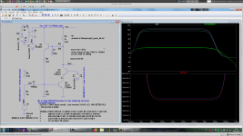
PSSR is not 0, but it is not much.
R1 delivers 1nV/rt Hz, it is amplified to 2 nV/rt Hz by the VcVS. (LT3042 performance)
The blue line is then the contribution of the 2nV/rt Hz on Vcc to the output.
Abt. 20 pV/rtHz referred to input.
R1 delivers 1nV/rt Hz, it is amplified to 2 nV/rt Hz by the VcVS. (LT3042 performance)
The blue line is then the contribution of the 2nV/rt Hz on Vcc to the output.
Abt. 20 pV/rtHz referred to input.
Attachments

Last edited:
PSSR is not 0, but it is not much.
R1 delivers 1nV/rt Hz, it is amplified to 2 nV/rt Hz by the VcVS. (LT3042 performance)
The blue line is then the contribution of the 2nV/rt Hz on Vcc to the output.
Abt. 20 pV/rtHz referred to input.
That's kind of a "noise gain" not PSRR. For PSSR=dVo/dVcc use an AC source as power supply, set Vac=1V and Vdc=Vcc. Then frequency sweep the AC and see what you get heraus. That's the PSRR. My back of napkin calculation shows a PSRR of 1, that is, 0dB at the output. Of course, if you divide this by the stage gain, you get some "input referred" PSRR, but that would be a strange metric.
I've learned that 1/f is because of the carrier interaction with the lattice vibrating phonons [Van der Ziel], carrier density fluctuations
As of popcorn noise, my understanding it is mostly because of heavy ion
There are theories treating 1/f as a continuum of GR behavior, I don't have my references here but they exist. The point about popcorn is that the transitions often involve many carriers and there is no predicting the spectra.
The point about popcorn is that the transitions often involve many carriers and there is no predicting the spectra.
But not Auger recombination, no? (I've been out of device/noise modeling for a decade, sorry if I'm being dumb 🙂)
I need to bone up but I'll give this a go: https://engineering.purdue.edu/~saeedm/j2.pdf
PSSR is not 0, but it is not much.
R1 delivers 1nV/rt Hz, it is amplified to 2 nV/rt Hz by the VcVS. (LT3042 performance)
The blue line is then the contribution of the 2nV/rt Hz on Vcc to the output.
Abt. 20 pV/rtHz referred to input.
And BTW, using the same expensive ZTX851 for the cascode is a not needed luxury; the cascode device doesn't need to be low noise, it's contribution to the input referred noise is very small. Any medium power device in TO252 and a little bit of PCB copper for cooling will do in that position.
But not Auger recombination, no? (I've been out of device/noise modeling for a decade, sorry if I'm being dumb 🙂)
I need to bone up but I'll give this a go: https://engineering.purdue.edu/~saeedm/j2.pdf
Again if memory serves, Van Vliet studied the GR noise in intrinsic photoconductors for the case of band-to-band Auger radiative recombination.
I'm pretty sure the Auger radiative recombination can safely ignored in our day to day semiconductor devices. It could be important for photodiodes or PIN diodes, though.
Again if memory serves, Van Vliet studied the GR noise in intrinsic photoconductors for the case of band-to-band Auger radiative recombination.
The bottom line is that little of the theory led to solutions, we went along scribing the back of wafers and turning knobs for years.
- Home
- Design & Build
- Equipment & Tools
- My version of the G = 1000 low noise measurement amp (for Ikoflexer)