Jack, the resistor "R3" placed between the input JFET's source, and ground, is for DC bias purposes. R3 is chosen to give the desired drain current (5mA). R3 is bypassed with a whopping great capacitor "C3" in order to increase the AC gain of the input stage at 0.1 Hertz (!!) which is the design target for LF response.
Without C3 the AC gain is [ R2 / (R3 + (1/gm)) ] . . . . but when C3 is included, the R3 term disappears: gain is now [ R2 / (1/gm) ]
Without C3 the AC gain is [ R2 / (R3 + (1/gm)) ] . . . . but when C3 is included, the R3 term disappears: gain is now [ R2 / (1/gm) ]
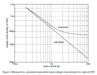
Noise is inversely related to drain current, until the JFET self-heats. This was shown by Sam in Figure 3 of his LA article. The source resistor plays two parts setting the current AND contributing Noise ER(s) = SQRT (4kTR).
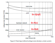
In Sam's article, the current is set by a low noise current source with high impedance at what he determined to be "optimal" given the heating effect. He uses an array of resistors with a paralleled value of 0.989 Ohms (Rs) and the gain-setting resistor for the feedback network.
So the question is, do the noise components simply sum, or sum to the square root of the sum of the squares?
Attachments

What is part number/ type C5 & C2?
To have 1nV across 56M resistor, leakage has to be < 18E-18 A.
And what is the gain of JFET stage alone, measured w/o NF, I mean ratio ac at gate to ac at drain?
To have 1nV across 56M resistor, leakage has to be < 18E-18 A.
And what is the gain of JFET stage alone, measured w/o NF, I mean ratio ac at gate to ac at drain?
I think 1nV offset at in input is not relevant.
But enough current noise through the input bias resistor might limit the noise performance. We can calculate current noise from bias current via sqrt(2 * e * Ib). Now it is up to you to calculate the required maximum bias current….
But enough current noise through the input bias resistor might limit the noise performance. We can calculate current noise from bias current via sqrt(2 * e * Ib). Now it is up to you to calculate the required maximum bias current….
Please correct me if I’m wrong but I think the limit for less than 1nV/sqrtHz over 56Meg is about 1 femto ampere…. Which is about 6000 electrons per second ?
C2, C5 -- a nice polypropylene cap for each.What is part number/ type C5 & C2?
To have 1nV across 56M resistor, leakage has to be < 18E-18 A.
And what is the gain of JFET stage alone, measured w/o NF, I mean ratio ac at gate to ac at drain?
Gain of a JFET stage is given by:
A = Rd / (Rs + 1/gm)
- Home
- Design & Build
- Equipment & Tools
- My version of the G = 1000 low noise measurement amp (for Ikoflexer)