Jackinnj: > Thankfully, I don;t have to do this for a living...
So do I; I'd be broke by now 😱
If you measure into the gate, you see minus ?40? Ohms in series with some
capacitance. Add the right inductor and it will oscillate in series resonance.
The only easy cure is a positive resistor that is larger than the negative one.
But that is against the idea of a low noise amplifier.
by the way, the above circuit needs a buffer to drive the feedback. A VCVS
is nice, a BUF634 works nearly as good. The source then does no more lag
the input, the capacitive loading of the source is gone, it simulates nicely.
But the network analyzer says the input impedance is negative over part of
the frequency range.
I want a solution without gate stoppers but I have shelved it until I get a new idea.
Instead I have continued on the chopper amplifier and experimented with step up
transformers. I have tried to modify commercial ferrite transformers to get
a higher turns ratio, but then they no longer work as transmission line xfrms,
have lots of stray inductance and everything rings like hell when the analog
switches do their switching.
I have found a solution with 2 cascaded transformers, each with z=1:9.
That works reasonably; still there are some transients that are asymmetric
and that gives me some offset at the output. I'm just trying to short the
op amp input during the transient phase. The CPLD that makes the
clocks for the switches can easily generate the blanking pulse also.
Carl Battjes Darlington: There is a discussion of that in
Hollister, "wideband amplifier design"
Last edited:
Thanks, Dimitri!
In principle yes, but I have done some experiments without much success.
Peter Staric and Erik Margan have a section on this in their wideband amplifier book
beginning at page 3.89. Even more detailed than Margan's text above.
That is like trying to drink from a hydrant. 🙂
S/M warn that the compensation really works only for small signal; I cannot
dim the vector network analyzer much below -60 dBm or the trace gets noisy.
Maybe that's part of the problem.
Hollister, Battjes, Staric and Margan all seem to have been in Tektronix's
vertical amplifier development. That must have been an interesting place to be.
Their books:
< Bot Check >
and
< Bot Check >
Both are really good.
Last edited:
Thanks for that.
Found a slightly flatter copy here: http://techdoc.kvindesland.no/radio/passivecomp/20061223155128957.pdf
If I've drawn this correctly:
I am impressed by the photovoltaic MOSFET driver solution.
I do not have VO1263 yet, so I made an experiment with a single blue LEDs as a light sources and a single infrared diodes as a photovoltaic elements, see the picture below. I know it looks stupid, but I'm trying to understand how it works. System is sensitive to ambient light.
Best Regards,
Andrzej
Attachments

Last edited:
. System is sensitive to ambient light.
Best Regards,
Andrzej
Mark Johnson paints them with black nail polish -- you'll need to find a "goth" girlfriend if you're to embarrassed to buy black nail polish at the drug-store.
You will want to put the emitter/detector in close proximity, or enclose both in the same piece of shrink tubing so that they thermally cycle together.
Decades ago (the story was related in "Analog Dialogue) a mysterious source of noise troubled engineers at ADI -- it turned out that a lowly and clear 1N4148 was being modulated by fluorescent lights.
Hi Jackinnj,
Thank you very much for response!
Blue light is nice...
From the point of view of keeping the marriage monolith in good condition, black shrink tubing is less risky 🙂.
a.
Thank you very much for response!
Blue light is nice...
From the point of view of keeping the marriage monolith in good condition, black shrink tubing is less risky 🙂.
a.
Mark Johnson paints them with black nail polish -- you'll need to find a "goth" girlfriend if you're to embarrassed to buy black nail polish at the drug-store.
That's easy. I can get it from my 17yo daughter.
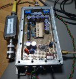
I have just made a new low noise preamp.
First I tried the differential amplifier from Art of Electronics 3 with the
64 ZTX851. That worked in principle, but the bias was to sensitive
against everything, esp. temperature and source resistance. That
will work for a fixed application like Win's ribbon microphone, but
it's a nightmare for a measurement amplifier.
The advantage is that one does not need a coupling C, but if you want
to measure the noise of a reference etc, you need a C anyway. And
then you need a low impedance bias resistor that needs the C to be
really big.
Since I could not avoid the C, I choose the single ended version
that needs only a quarter of the transistors and the biasing with
the npn like in Win's proposal.
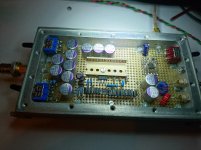
I inserted a 2SC3420 cascode since I found the bandwidth to be lacking.
50 KHz or so with a 50 Ohm source but then this amplifier does not
make sense after a 50 Ohm source for voltage noise reasons.
With a low impedance source it has > 2 MHz BW with a slight
peak above which is for further study.
There are two ADA4898 stages to bring the gain to 60 or 80 dB.
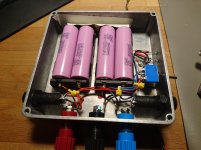
I run the 16 ZTX851 at ca. 190 mA from +/- 6.9V lithium cell pairs.
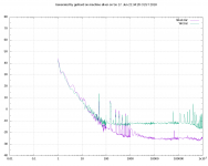
The input can be open, shorted and 6 Ohm as a noise reference.
6 Ohms delivers 100 pV/root Hz.
The shorted amplifier features abt. 14 dB less than the 6 Ohms.
12 dB less would be 50 pV/root Hz, so it should be even 2 dB better
than that, but take that with a grain of salt.
Most of the 1/f noise goes on the FFT analyzer. I cannot turn the
preamp gain much higher without overdriving it. I have made a
small board with a LTC2500-32 that I will marry to a BeagleBoneBlack
to replace the FFT analyzer for this job.
The fuses in the battery box are important. The Lithium bombs
provide 30 A easily.
First I tried the differential amplifier from Art of Electronics 3 with the
64 ZTX851. That worked in principle, but the bias was to sensitive
against everything, esp. temperature and source resistance. That
will work for a fixed application like Win's ribbon microphone, but
it's a nightmare for a measurement amplifier.
The advantage is that one does not need a coupling C, but if you want
to measure the noise of a reference etc, you need a C anyway. And
then you need a low impedance bias resistor that needs the C to be
really big.
Since I could not avoid the C, I choose the single ended version
that needs only a quarter of the transistors and the biasing with
the npn like in Win's proposal.
I inserted a 2SC3420 cascode since I found the bandwidth to be lacking.
50 KHz or so with a 50 Ohm source but then this amplifier does not
make sense after a 50 Ohm source for voltage noise reasons.
With a low impedance source it has > 2 MHz BW with a slight
peak above which is for further study.
There are two ADA4898 stages to bring the gain to 60 or 80 dB.
I run the 16 ZTX851 at ca. 190 mA from +/- 6.9V lithium cell pairs.
The input can be open, shorted and 6 Ohm as a noise reference.
6 Ohms delivers 100 pV/root Hz.
The shorted amplifier features abt. 14 dB less than the 6 Ohms.
12 dB less would be 50 pV/root Hz, so it should be even 2 dB better
than that, but take that with a grain of salt.
Most of the 1/f noise goes on the FFT analyzer. I cannot turn the
preamp gain much higher without overdriving it. I have made a
small board with a LTC2500-32 that I will marry to a BeagleBoneBlack
to replace the FFT analyzer for this job.
The fuses in the battery box are important. The Lithium bombs
provide 30 A easily.
Attachments
Last edited:
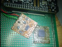
The ADC module contains the LT2500-32, lt6655 reference, 2 * LT3042 regulator, -3V regulator and the fully balanced ADC driver in abt. 1 square inch. But there is still a lot to do, esp. software on the Beagle Bone Black.
The amplifier is really intended as a test balloon for the stage after the chopper in a different design. There, at 500 KHz the size of the coupling Cs does not hurt anymore. That board is home-etched. What the laser printer can print that can be contact-copied to presensitized FR-4.
The amplifier is really intended as a test balloon for the stage after the chopper in a different design. There, at 500 KHz the size of the coupling Cs does not hurt anymore. That board is home-etched. What the laser printer can print that can be contact-copied to presensitized FR-4.
Attachments

Last edited:
The input can be open, shorted and 6 Ohm as a noise reference. 6 Ohms delivers 100 pV/root Hz.
10ohm is 0.4nV/rtHz, 100pV/rtHz=0.1nV/rtHz is 0.6ohm. 6ohm is 0.31nV/rtHz.
Your amp seems to have 50pV/rtHz (14dB under 0.3nV/rtHz which is a little lower than what I would expect from 16 low noise bipolars. It amounts to 0.2nV/rtHz per device, or a Rbb of 2.5ohm (probably slightly lower, since Rbb is not really the only contributor). But noise corner frequency is what I would expect.
Unfortunately, you know the price: current noise is SQRT(2*q*Ib) which in your case is (assuming a beta of 200, datasheet typical for these ZTX851 devices) that comes to 18pA/rtHz. It follows that a 3ohm source resistance already equals the 50pV/rtHz voltage noise, or that you have to keep the source resistance lower than about 1ohm to be able to ignore the amplifier current noise contribution. Good for batteries measurement, but that's all about it...
If you could measure the current noise, I would really appreciate, it would save me some work to measure these ZTX851 devices... It's easy if you already have the prototype.
You are completely right, I was surprised myself, therefore the grain of salt. I should leave away the Rioja when posting.
Cheers!
PS The chopper board has ZXTN2018 in sot -23, they have the marking "851", so I'd assume there is the same chip inside.
Cheers!
PS The chopper board has ZXTN2018 in sot -23, they have the marking "851", so I'd assume there is the same chip inside.
If you could measure the current noise, I would really appreciate, it would save me some work to measure these ZTX851 devices... It's easy if you already have the prototype.
Make a proposal to the setup, so we have a comparable environment.
or that you have to keep the source resistance lower than about 1ohm to be able to ignore the amplifier current noise contribution. Good for batteries measurement, but that's all about it...
or for reading out squids, zeroing bridges, interferometers, phase noise detection
after a switching mixer...
and all that without the $20 line filter of The Giant.
Make a proposal to the setup, so we have a comparable environment.
- Short the input with a few known resistors, say 1ohm, 2.2ohm, 3.3ohm, 4.7ohm, 6.8ohm, 10ohm, and record for each the input referred noise @1KHz (divide for each the output noise to the known amplifier gain @1KHz)
- Plot the measured squared values (in pV^2/Hz) vs. the squared values of the input resistor.
- Verify that the plot is approximately a straight line, interpolate the data using Excel best squares fit for a straight line.
- Verify the Y axis intercept value is the square of the amplifier voltage noise (previously determined from a input shorted measurement like you already did).
- Calculate the straight line slope (or use the regression result in Excel). This slope is the square value of the input current noise. Should be in the18pA/rtHz ballpark.
If it's too complicated, just determine the spot value of the noise for, say, a 3.3ohm input resistor and calculate the current noise in that point, In~SQRT(measured input referred noise^2 - amplifier input referred noise^2 - 3.3ohm resistor Johnson noise^2)/3.3ohm
or for reading out squids, zeroing bridges, interferometers, phase noise detection
after a switching mixer...
and all that without the $20 line filter of The Giant.
Do you get random fluctuations at very low frequencies (like a few hertz)? This was for me a killer in single ended, high gain, low noise amplifiers. I found no way to avoid these fluctuations (allegedly of thermal origin) to occasionally saturate the output but limiting the low frequency bandwidth to some 10-15Hz. Doesn't happen in differential amps, but then the 3dB noise penalty is there...
And if I'm allowed to ask, how did you balance the 16 devices collector current? That would need some emitter resistors to balance the collector currents and avoid current hogging but then in this case even 1ohm (10mV delta V) could be too much from a noise perspective...
At 10 Hz, I really cannot say. My Agilent 89410A/411A has outrageous 1/f in that range; I even tried cross FFT via two channels, that seemed overly optimistic. I don't know where the noise comes from, therefore the experiment with the LTC2500-32. With it, I have clock phase noise etc under control. Some people claimed that channels 1 and 2 of their 89410A were vastly different, I cannot say that from mine. For the measurements this evening, I put the lid on the box but did not use the screws; I first must find 100U caps that are 0.5mm lower. But moving air from me working at the table can probably be excluded.
I did not do anything to balance the transistors, any emitter resistor is too much at this level. For FETs it's hopeless because of the lower gm. But then, even for FETs, imbalance means only that you don't get the full advantage, maybe an input C penalty, but it is not like that one mushroom will spoil the whole pot.
The Zetex spice models seem also to be optimistic modeling 1/f. I got that amplifier working just today, so it is probably premature to draw final conclusions.
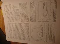
Art Of Electronics III has plots of Vbe for the Zetexes; I include the relevant pages. They cannot replace the book, so I hope Winfield will forgive me when I meet him on usenet sci.electronics.design. One cannot survive without this book anyway.
I did not do anything to balance the transistors, any emitter resistor is too much at this level. For FETs it's hopeless because of the lower gm. But then, even for FETs, imbalance means only that you don't get the full advantage, maybe an input C penalty, but it is not like that one mushroom will spoil the whole pot.
The Zetex spice models seem also to be optimistic modeling 1/f. I got that amplifier working just today, so it is probably premature to draw final conclusions.
Art Of Electronics III has plots of Vbe for the Zetexes; I include the relevant pages. They cannot replace the book, so I hope Winfield will forgive me when I meet him on usenet sci.electronics.design. One cannot survive without this book anyway.
Attachments
Last edited:
FETs don’t current hog, and any current imbalance is irrelevant anyway from a noise perspective. Bipolar do current hog and without emitter resistors they may get into thermal runaway, in particular in a closed box without venting, and then at least take down the noise performance. But perhaps these ZTX devices are very well matched if from the same tube.
Some FETs may have crazy high noise (GR excess noise, on top of the ubiquitous 1/f noise, at very low frequencies) and for those indeed one paralleled mushroom will take down the whole pot.
Must sleep a bit.
Some FETs may have crazy high noise (GR excess noise, on top of the ubiquitous 1/f noise, at very low frequencies) and for those indeed one paralleled mushroom will take down the whole pot.
Must sleep a bit.
- Home
- Design & Build
- Equipment & Tools
- My version of the G = 1000 low noise measurement amp (for Ikoflexer)