Hey guys, this is the philosophy of these threads. Its not about achieving something but about playing and learning and building.
I couldn't agree more.
However, while learning and playing, one should also learn how to receive criticism, credit other people work and/or ideas, ask questions, and shouldn't jump to advertise to sell boards and devices by the pack, in particular at outrageous prices, in a supposingly technical thread (when a group buy thread was on purpose created by someone else in the appropriate place).
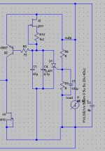
I've seen a new schematic floating around, looks a little better, but only 5pF as compensation will do nothing against the stability issues. A regulator is almost never driving pure resistive loads, that's why healthy phase and gain margins are mandatory, usually > 60 degs and 5-6dB. Then another lesson learned is going to be about trades between stability and performance.
What about a rather high -Vto Jfet feeding a few Leds with an RC filter in the junction, C tied to +V than ground? Since this is about a low voltage out reg ver, not many leds will be needed and can be less in self noise and harmonic noise pick up than any 30% Idss (about) Tc stabilized Norton Vref. You would just need to lift the Vbe that the Jfet nests in with a couple of leds so to achieve 2X-Vto Leds's Jfet CCS for it not to wobble.I too wish there was a better Vref option, if you come across one please give me a shout. 🙂
How about replacing R11 with a TL431 (or similar reference)?
Taking it a step further, the input of the TL431 could be fixed to the output, and coupled to Q2 with a low pass filter (rather, slow it down a whole lot because it would just dump indefinite current into the low pass) so that the TL431 manages the output voltage, and the regulator focuses on Zout. (TL431 for DC, Ikoshunt for AC)
- keantoken
Attachments
kt, I'd worry about noise with the tl431. Would you not? Maybe the ts431 by Taiwan Semi would work here. In any case, it is a solution. For the low voltage version there are several very low noise voltage references that one could use, buried zener, etc.
Salas, this reminds me of the solution you were discussing with syn08 in the JC thread, is that it? If so, I have a different opinion about it the exact implementation. I still could raise the current a bit and use just LED+R in the low voltage version, sure.
syn08, I don't even know where to start with you. I specifically say that this circuit has a phase margin of over 65 degrees and your comment is "only 5pF as compensation will do nothing against the stability issues."
Stability issues? Maybe psychological. Dude, please get off your high horse, lose the attitude, and then come back. Nothing gives you the right to treat people the way you do. If you want to contribute and help people, put some thought in what you say and even more thought in HOW you say it. However, if you got Asperger's please accept my sincere apology, since you can't help it.
I wanted to throw that idea in anyways. I would think most noise could be filtered out with RC filters, except at low frequencies (but I don't think that fits with the philosophy here).
What about turning Q2 into a NTP/Rush and feeding the other input with a reference?
Syn08, I would advise unblocking Iko's posts lest you embarass yourself more. In any case, those who have been participating here for the last several pages could care less what you have to say because they've been following Iko. The last schematic you posted (post 606) had some critical errors, which I'm guessing you didn't realize since you can't see Iko's posts. I doubt that anyone who saw that is taking you seriously right now.
- keantoken
I must amend my previous post, I really have no idea what the others here think as opposed to
Sorry for the mistake,
- keantoken
those who have been participating here for the last several pages could care less
Sorry for the mistake,
- keantoken
I haven't really kept up with the development of this thread and am, as a result, a little out of touch with where the group buy is just now. What's the latest? I checked the Wiki but there isn't any mention of dates on there. Apologies if my is answered somewhere else.
Thanks,
Carl
Thanks,
Carl
this shows how you design, what your thoughts are and how you make decisions when choices/compromises must be made.I guess I'm over-explaining my choices a bit too much.
I'm a big fan of simpler circuits actually.
Many designers do this and all do it slightly differently, but ultimately they reach a conclusion that, for them, minimises the downsides and maximises the upsides within their budget. That budget could be weight, or volume (size), or cost, or heat, or simplicity, etc.
I think much of what is good about DIYaudio is the range of abilities that exist here. I like to see why something works, I like to understand and learn.
I like to see how the designers arrived at their choice of devices and operating parameters and why one device gives a better set of compromises than another device.
Danley's Labhorn paper, there are hundreds of others, show why he chose to go that particular route. It is an exemplary paper that shows the professional designer at his best.
I see nothing wrong with explaining why you did something. We may or may not agree but that does not matter, what matters is that we understand why the designers chose to do it that way. If we can understand we can progress from there.
Long may the designers reveal their secrets. It's them that we learn from.
Iko and Salas,
keep up the good work.
Last edited:
I haven't really kept up with the development of this thread and am, as a result, a little out of touch with where the group buy is just now. What's the latest? I checked the Wiki but there isn't any mention of dates on there. Apologies if my is answered somewhere else.
Thanks,
Carl
Hi Carl,
I've sent boards to Salas and Stormsonic so they can build the regulator and play with it. If people still have an interest in getting the boards after they report back, I'll just order them. Sorry, no specific dates yet.
I would also like to offer a public apology for my stupid comment earlier; I'm not a medical doctor and I should refrain from medical diagnoses.
Salas, this reminds me of the solution you were discussing with syn08 in the JC thread, is that it? If so, I have a different opinion about it the exact implementation. I still could raise the current a bit and use just LED+R in the low voltage version, sure.
Yes, that is what I use in the phono first stage cascode for biasing the top transistor's base, and it was measured superior to several Nortons in that thread discussion point on Syn08's HP gear too when I proposed a test. What is your opinion about it in the lowV reg's Vref?
Attachments
Hi kt,
you're right about filtering the noise. For instance when I was using a zener, I found that a 1000uF bypass cap got the noise very very low (visually on the scope). But there was still a bit of "grass" tips and was happier to use the jfet solution. Just a personal preference. I haven't tried a tl431 yet, though I got a bunch of them at home. I probably will, besides a few other ideas that I got in improving the regulator. At the moment I have more directions than time to pursue them.
I don't know kt, how does this fix the reference? I'm not dismissing your idea, but unless there is a significant benefit, I would be reluctant to add complexity.
I wanted to throw that idea in anyways. I would think most noise could be filtered out with RC filters, except at low frequencies (but I don't think that fits with the philosophy here).
you're right about filtering the noise. For instance when I was using a zener, I found that a 1000uF bypass cap got the noise very very low (visually on the scope). But there was still a bit of "grass" tips and was happier to use the jfet solution. Just a personal preference. I haven't tried a tl431 yet, though I got a bunch of them at home. I probably will, besides a few other ideas that I got in improving the regulator. At the moment I have more directions than time to pursue them.
What about turning Q2 into a NTP/Rush and feeding the other input with a reference?
I don't know kt, how does this fix the reference? I'm not dismissing your idea, but unless there is a significant benefit, I would be reluctant to add complexity.
Keep in mind that TL431 is reported to be at its best for self noise at 1mA if you ever practice it.
Yes, that is what I use in the phono first stage cascode for biasing the top transistor's base, and it was measured superior to several Nortons in that thread discussion point on Syn08's HP gear too when I proposed a test. What is your opinion about it in the lowV reg's Vref?
I don't see why it would not work, and it's very easy to do on the same PCB. In theory, the output impedance gets adversely affected, but it's probably not noticeable in practice. Question, how much of an improvement is the Led tempco vs the jfet Vref? Probably significant.
Here's a nice table with some properties of LEDs, colour, Vf.
Technical LED Color Chart
The main benefit if there is significance in the big picture would be its tendency not to pick up harmonic noise since the impedance of the CCS will be nearer to the Led(s). If you lower the R and up the filter cap to 1000uF maybe the Zout can be helped? Leds are ''stiff'' as voltage references.
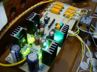
Oh yeah, I like glowy things too 😀
I might give it a try tonight if I find a bit of time. The huge capacitor isn't exactly great but... you can't have it all.
It's good we have the option, really. Then people can experiment and see which sound they like.
I might give it a try tonight if I find a bit of time. The huge capacitor isn't exactly great but... you can't have it all.
It's good we have the option, really. Then people can experiment and see which sound they like.
In practice I have found that the theoretical Zout hit when using a smaller cap and a largish R is swamped by the layout and cabling. In the DCB1S it works great with just 100uF quality cap and its a DC coupled buffer. How much it ups Zo in your sim if with a moderate cap?
- Status
- Not open for further replies.
- Home
- Amplifiers
- Power Supplies
- My take on a discrete shunt voltage regulator