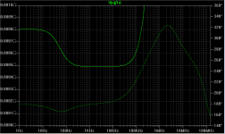
Not much, a really large cap only flattens the curve a few dB at the lower frequencies. With a smaller cap it looks more like a step.
Edit: 100uF cap, Zout plot
Edit: 100uF cap, Zout plot
Attachments
Last edited:
A 0.0003 analysis dif could be swamped in a real build very possibly. Was that with just the cap across, or RC with 100R? OTOH leds are for fixed Vout regs only.
I use Leds and Jfet in the DCB1S. I find them practical up to some volts (+/-10 there) in fixed regs, since it does not take many. In my opinion they are the most dynamic and clean subjectively. Plus they glow! I like.😀
Nice build! I guess it is v1.
I have heatsinks that are similar to be used. What is the maximum heat dissipation with those heatsinks? Say 10V over the CCS, what is the maximum current they can take?
Edit: opps! the photo on the previous page was not quoted.
Last edited:
I mentioned a couple of days ago that my scope showed some 500uV - 800uV peak to peak ripples even when the probe touched the ground wire on the ground of my preamp.
I had some time to look at the problem today. It took me 5 minutes to work out that my scope and the preamp were connected to different power sockets / outlets. When they were connected to the same power socket the ripples were gone. This must be the case when I measured 5a. Ground loop was the devil.
I had some time to look at the problem today. It took me 5 minutes to work out that my scope and the preamp were connected to different power sockets / outlets. When they were connected to the same power socket the ripples were gone. This must be the case when I measured 5a. Ground loop was the devil.
Yes, a large cap there helps a bit. Who's going to try it out? 😀
Today I spent half a day using my scope to measure my power amp PSU and playing with different configurations such as C, LC, LRC, CLRC, etc, after the rectifier bridge. I learnt a great deal from it.
I have 3 x 10,000uF on the rail. These are 100V computer grade low impedance low ESR type. The output from the garden variety 600V 35A bridge looks absolutely horrific (but the Fairchild Stealth 600V 30A for my preamp looks smooth). However, after those large caps, it looks a lot better, only a tiny bit of high frequency generated from the rectifier bridge gets through. When the probe got into the 0.1uF local bypass on the board, the ripples were gone.
So the scope does show that capacitors are quite effective, up to a few MHz probably. Beyond that my scope can not measure.
HiFi,
would you do us a big favour now that you have your test arrangement working as well as you want.
Would you add a 1uF metallised polypropylene across the transformer secondary and tell us if anything changes at any of the test points.
If this first cap shows no deleterious effect, can you add a second cap, 0.1uF metallised polyester across the rectifier + to -. Tell us what you find.
I mentioned a couple of days ago that my scope showed some 500uV - 800uV peak to peak ripples even when the probe touched the ground wire on the ground of my preamp.
I had some time to look at the problem today. It took me 5 minutes to work out that my scope and the preamp were connected to different power sockets / outlets. When they were connected to the same power socket the ripples were gone. This must be the case when I measured 5a. Ground loop was the devil.
He-he! Most often a ground loop is the culprit. Your ears didn't lie to you! Good job!
 I'm glad you fixed it.
Nice build! I guess it is v1.
I have heatsinks that are similar to be used. What is the maximum heat dissipation with those heatsinks? Say 10V over the CCS, what is the maximum current they can take?
Edit: opps! the photo on the previous page was not quoted.
That one is from the builds galley. Its CRT's, and the the regs are LED Vref V1 symmetric. Those sinks can get about 2.5W each.
Hey guys, I've been asked privately if the PCB would work for high voltage, as in TUBES 😀
I think this is a good question and probably others are wondering as well. The short answer is yes, but it's not a clean yes. Yes with a minor modification and of course, different parts.
The long answer is this. I've worked on a high voltage shunt regulator for quite a while, and it was there that I first tried the buffer and cascode, which later made it into the low voltage version. I still have a few prototypes from that time. Almost the same topology too. But then I got really involved in the lower voltage reg development and did not finish all the tests and optimization of the HV reg. It's in the works though. However, Salas has had a HV shunt reg for a long time, which has been built by many people, who are very happy with it! If I wanted an HV regulator right this hour that's the one I'd build.
HiFi,
would you do us a big favour now that you have your test arrangement working as well as you want.
Would you add a 1uF metallised polypropylene across the transformer secondary and tell us if anything changes at any of the test points.
If this first cap shows no deleterious effect, can you add a second cap, 0.1uF metallised polyester across the rectifier + to -. Tell us what you find.
Andrew,
I am not sure what this is to solve, as there is no problem now.
Do you mean 1uF MKP from each of the Transformer secondary windings to ground before the rectifier? or between the secondary windings? This is something I have not tried before.
0.1uF (ceramic) across the rectifier + to - is already in place. Actually, I am thinking about taking them out.
From my power amp PSU measurement, the 0.1uF MKP across the rectifier + to - does not seem to do much to reduce the big spikes. I am going to replace them with the Stealth.
After some LTspice modelling, and some actual listening, I now believe a LRC supply betters C, CLRC for my applications, both for the CCS-shunt regs and my power amps. Think about it, most circuits have high PSSR at lower frequencies, but low PSSR at high frequencies. All we need is a very small choke in the front to form a LP filter. Small inductance allows very small resistor for damping, so not to increase the PSU impedance much. In that case, I think the caps cross the rectifiers can easily do more harm than good, as it can cause ringing at certain frequencies. With the Stealth, there is possibly no need to use the caps across the rectifiers, as the datasheet suggests. This will probably give the quiest PSU at higher frequencies. Correct me if I am wrong.
Last edited:
It was your tip from the LV thread. Thanks a million.
In my preamp circuit, initially they were Schottky diodes 1n5822 (rated 3A). The sound was pretty good. Since my final circuit may draw 1A constant current, and I wanted to have sufficient reserve and did not want to overheat the 1n5822, I replaced them with garden variety 600V 35A. The sound was a big step backward and it was no longer good sound. Now I put in the Stealth. The datasheet does not say it is Stealth II, but the parameters seem to be very close. The sound is even better than the 1n5822.
I am about to put the Stealth to my power amp and see if it makes any subjective difference.
Do you mean 1uF MKP from each of the Transformer secondary windings to ground before the rectifier? or between the secondary windings? This is something I have not tried before.
0.1uF (ceramic) across the rectifier + to - is already in place. Actually, I am thinking about taking them out.
From my power amp PSU measurement, the 0.1uF MKP across the rectifier + to - does not seem to do much to reduce the big spikes. I am going to replace them with the Stealth.
The 1uF is across one secondary winding. Not to ground.
If you have a centre tap, it is one 1uF across the series connected windings.
If your have dual secondaries and dual bridge rectifiers, it is two caps, one 1uF across each secondary.
Does that compromise the measurements?
The 100nF ceramic may have sufficient esr to damp any tendency to ring, for the same reason I suggested MKS.
Try taking this off to see if anything improves or gets worse.
Earlier in this or salas' tread, I forgot where exactly, it is suggested to use a 40r - 60r in series to the cap to damp ringing. And this was over each coil....
The 100nF ceramic may have sufficient esr to damp any tendency to ring, for the same reason I suggested MKS.
...
not hassling BTW, just wondering; because my projects have been greenlighted a bit earlier than expected. I have enough regs to suffice in the meantime though
We are, we are 🙂
Both Salas and Stormsonic received the boards. When they finish testing no doubt they will let us know how it went. As I said before, because of the previous criticism the PCBs will not be ordered without tests being done by people other than me.
Both Salas and Stormsonic received the boards. When they finish testing no doubt they will let us know how it went. As I said before, because of the previous criticism the PCBs will not be ordered without tests being done by people other than me.
- Status
- Not open for further replies.
- Home
- Amplifiers
- Power Supplies
- My take on a discrete shunt voltage regulator