Great progress, but as I've been told: Please use the attachment function! I can't see any of the pics from https://lh3.googleusercontent.com/
If you wan't the pics to be inline with the text (instead of grouped at the bottom) you can use the paper clip button when making a post.
/Anton
type is too small this morning. I read your link too quickly; assumed it was pointing to some help or instructions. I googled the term and found there have been issues with images hosted on google. Most have to do with google discontinuing picasa support and replacing it with google photo and often manifests when images appear in emails..
All my inline images are stored in a shared album on google photo, not picasa, but I see their URLs contain.."google/user/content"/. I also hear there is cacheing involved on the google end so this problem might clear up on its own as caches local to you get updated. I don't know if I can fix it on this end; perhaps I can edit lower res attachments onto the posts.
Jack
Hi Anton:
I am using the "insert image" button, the one that looks like an envelope, to get images inserted in line with the text. This appears to work on both my laptop with Chrome browser and my android devices.. When I use the paperclip attachment button, as I did in the beginning of this thread, the images show up only as attachments at the bottom of the post.
BTW, that link to google didn't work for me.
If you are having a problem, it may be because these pictures and graphs are fairly high resolution. There may be a choke point between you and the google photo servers. I see that they are slow to load and so I'm going to dial that back in the future. Hope that helps,
Jack
I have same proplems as onni reading your pictures but only from post 109 and forward, well except very few ones they are all dead links.
Here one receipt to get images inserted in line with the text when you attach pictures with paperclip attachment button. In advanced editor before you use the yellow envelope button "insert image" that can be placed anywhere inside your text lines you have to attach your images with paperclip button and when hitting "Preview Post" button those attachments gets visual above your editor window, right click those thumpnails to "copy shortcut" that you insert into yellow envelope button "insert image". This way pictures get presented both inside your text lines and also at bottom of post, and attachment procedure ensure links will never go cold at this domain.
Last edited:
reposting 109 to fix images
Thanks for the tip, BRYTT
I've been meaning to connect a time reference loop back on my sound card for some time now but didn't get around to it until yesterday. Now the speaker sits directly on the garage floor as it will up in my listening room. It was time for another set of measurements.
My intention was to look at the IRs to determine the DSP delays needed for time alignment.
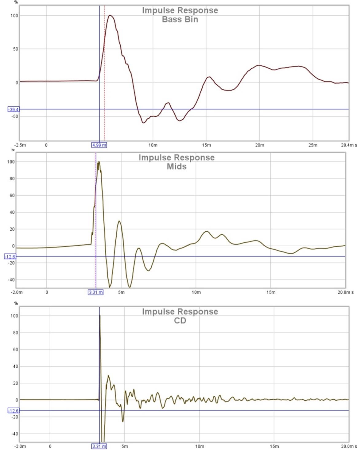
My first thought was just to let REW do the work and just read the delays off the cursor. This indicated that the MIDs and the CD each needed a 2 ms delay to align with the Bass Bin at 1m on axis. (Yes, a different delay will be needed out at the LP.)
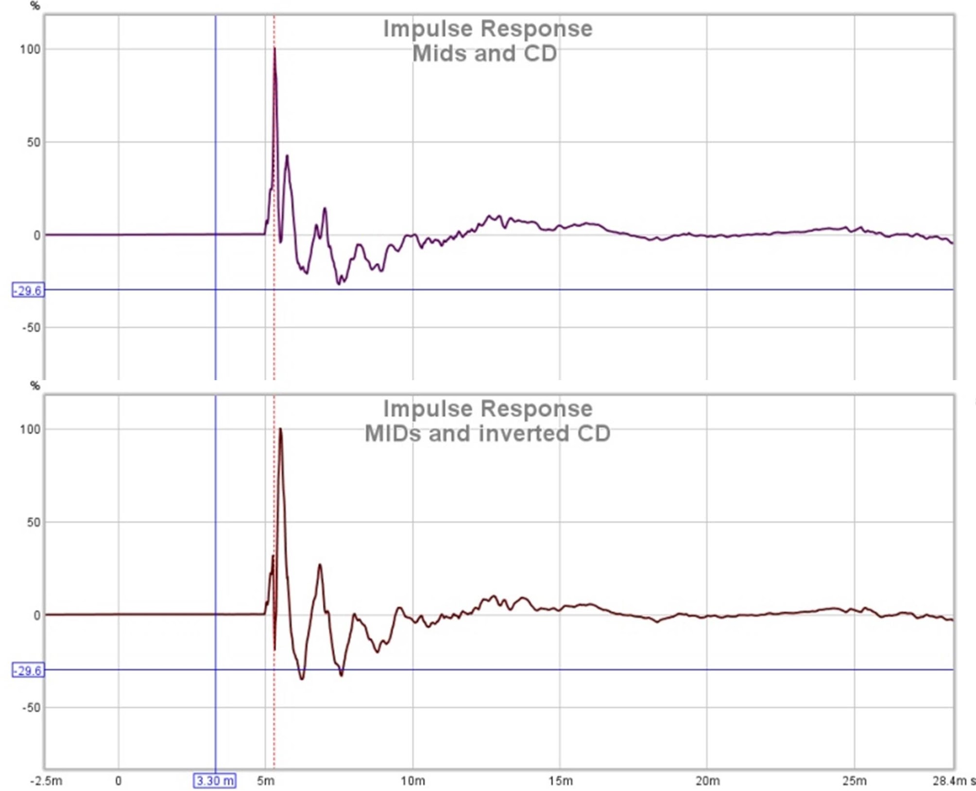
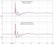
Dialing in those delays and remeasuring I saw that there was still a time offset between the mids and CD and a polarity issue as well:
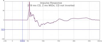
I next dialed in 2.19 ms delay for the CD and got this composite IR of all 3 drivers.
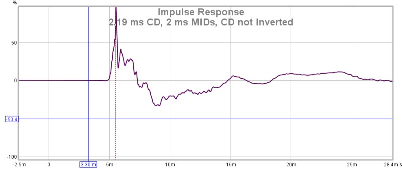
You've already seen how that looks in APL_TDA. I wish I had done this sooner!
Thanks for the tip, BRYTT
Attachments
reposting 110 to fix images
I made an XO using these time delays and prior measurements.
Here is the frequency response:
Here is its impulse response:
You can see some slight CD-mid driver time mis-alignment remaining. I was going to tweak this out but I got distracted by another anomaly. In this APL_TD display, note the group delay step and resonance at/around 300 Hz.
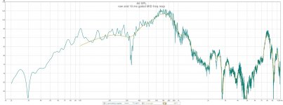
Note also the 324 hz null in my ungated, unsmoothed MID frequency response:
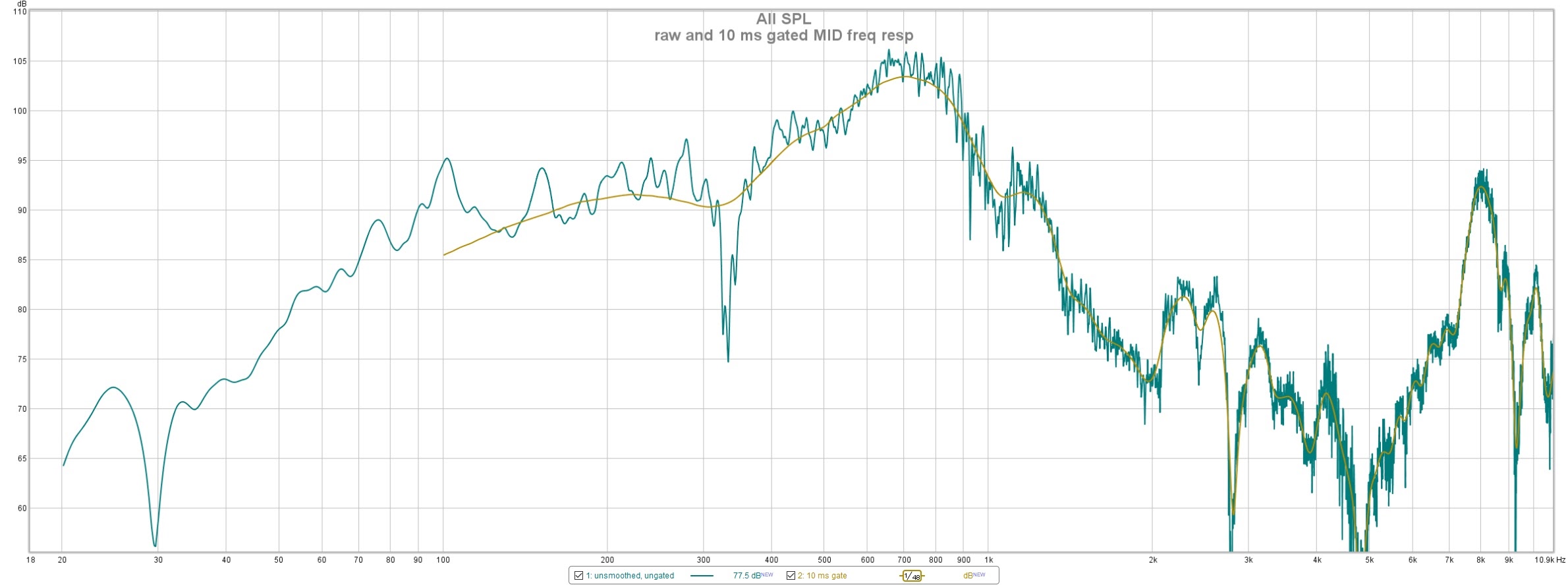
This null only appeared when I took the speaker off the dolly and set it down on the floor 6" lower. It starts disappearing when I set a gate at 20 ms and is gone completely with a 10 ms gate.
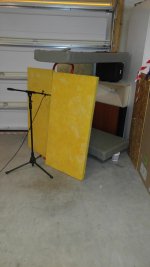
To find out where it was coming from, I set some fiberglass panels up behind the mic (hmmm, the sw compressed the picture vertically)
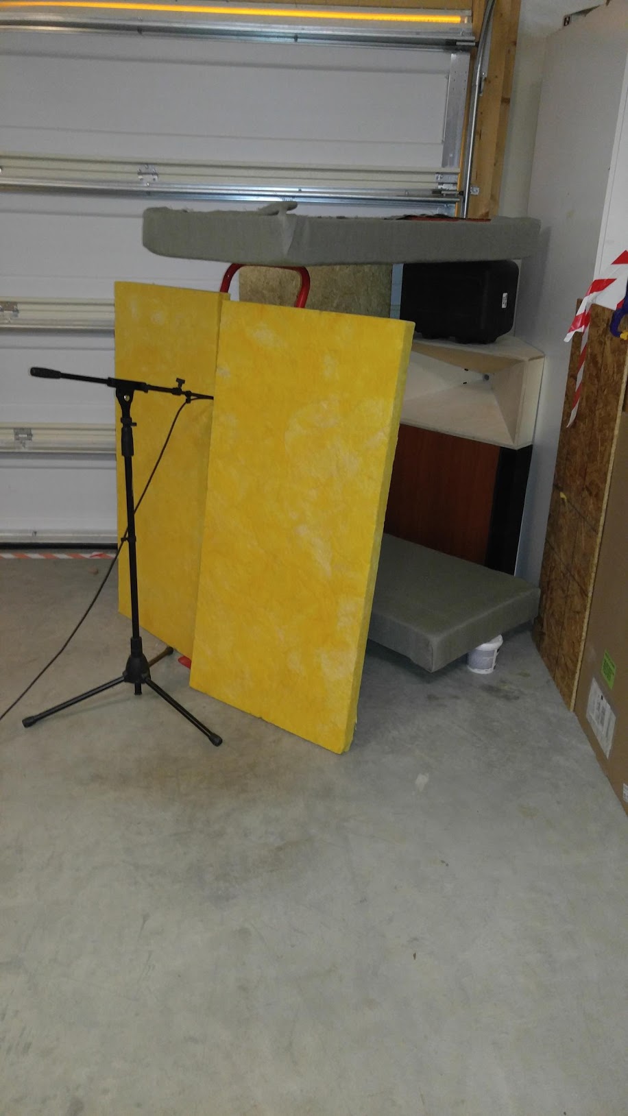
and then ran a APL_TDA sweep. Well there is nothing behind the mic within the implied distances except garage floor so this must be back scatter off the floor.
The resonance/reflection at around 300 Hz is now mostly gone.
Attachments
-
 Time aligned XO manual EQ Freq Resp.jpg201.9 KB · Views: 725
 -
 Time aligned XO manual EQ IMP Resp..jpg129.7 KB · Views: 681
 -
 TDA 3d TA XO 1m.jpg71.9 KB · Views: 674
 -
 raw and 10 ms gated MID freq resp.jpg189.7 KB · Views: 683
 -
 tweaked tda xo full range back of mic shielded.jpg70.4 KB · Views: 693
 -
 shield back of mic measurement setup.jpg133.2 KB · Views: 671
reposting 112 to fix images
Ceiling reflections are gated out so no need for the top absorber pad
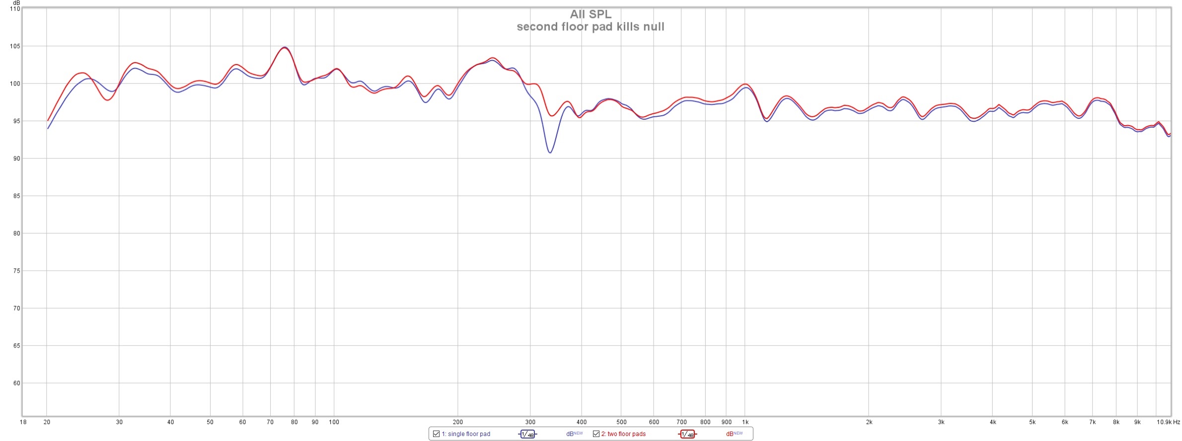
This morning I started over again measuring that original IR time aligned XO first with a single absorber pad directly in front of the speaker and next with a second absorber on the floor essentially in back of the mic.
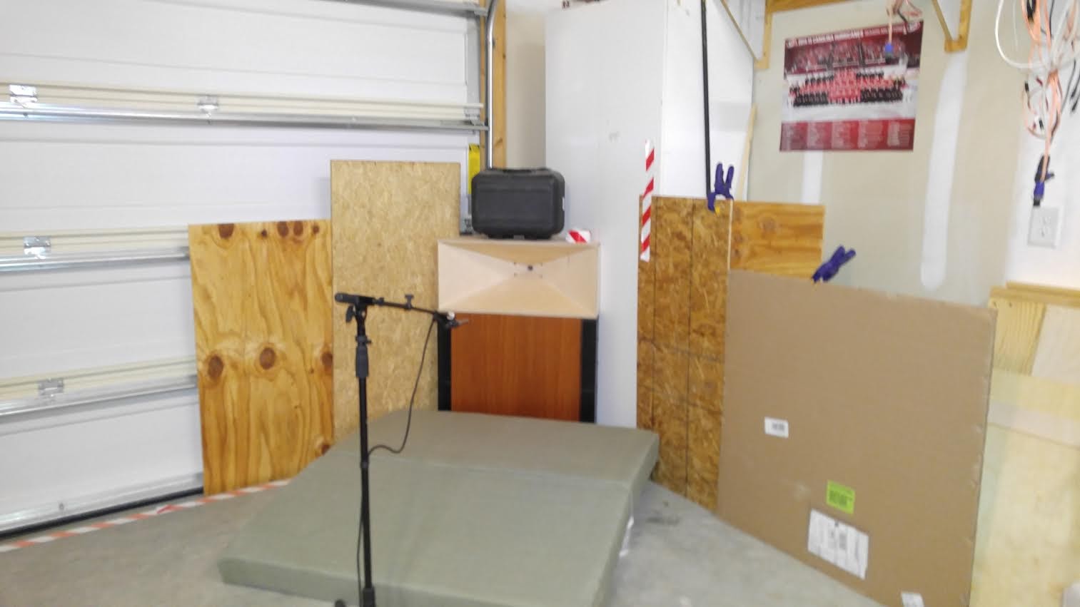
Here is a shot of the measurement setup
With absorption behind the mic, that null is gone.
Ceiling reflections are gated out so no need for the top absorber pad
Attachments

reposting 114 to fix images
I then re-tweaked the crossover, starting by dialing in the additional DSP delay I needed for the CD per the IR measurement. This introduced a small peak/dip at the 950 Hz XO that I reduced with a single PEQ. (edit: I did a few other EQ steps as well but not near the XO)
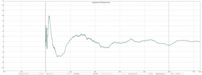
Here is an APL_TDA sweep of the final result.
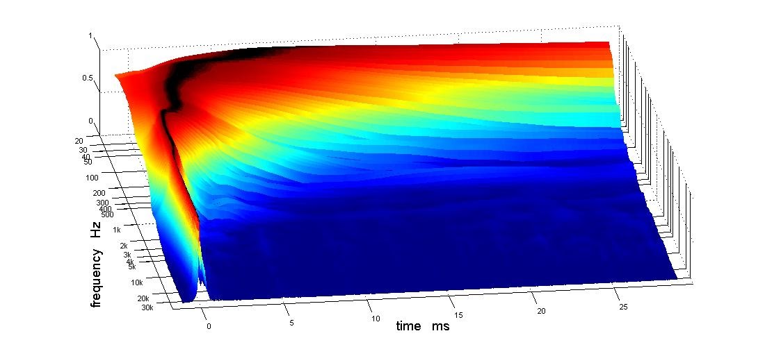
The delay through the 950 Hz CD/Mid XO is quite flat.
The 300 Hz resonance/floor reduction is still present but much reduced compared to bare concrete. In the listening room, I'll heavy padded carpet which probably won't do much to 300 Hz. I'm surprised the sound isn't scattered forward more away from the mic.
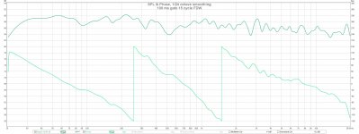
Here is the frequency response:
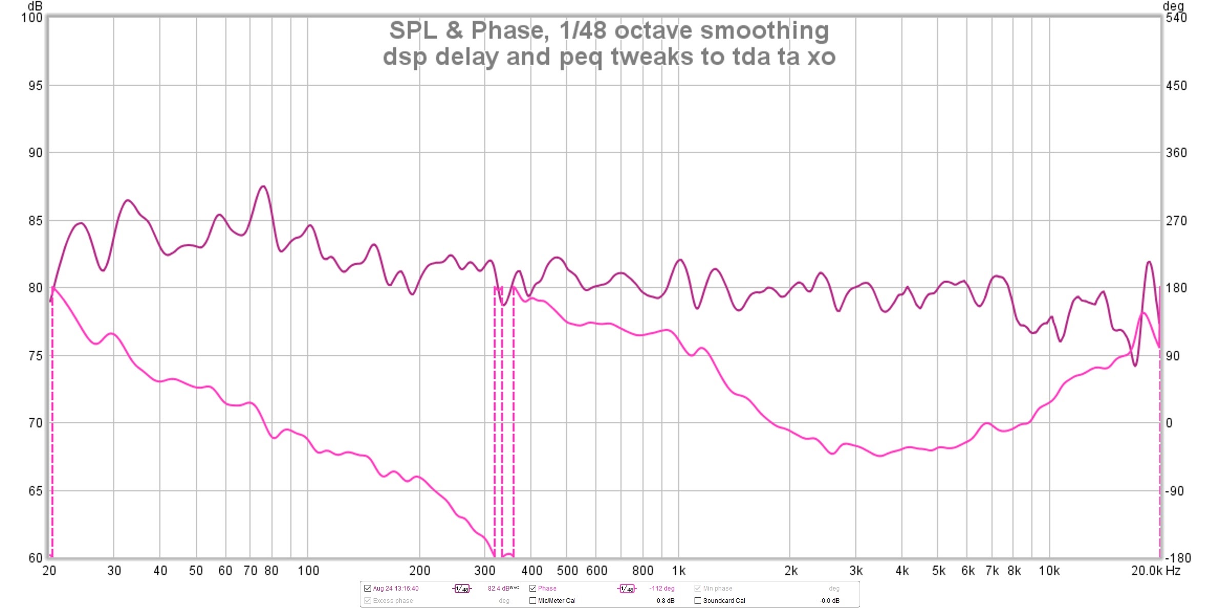
Here is the same response with ERB smoothing:
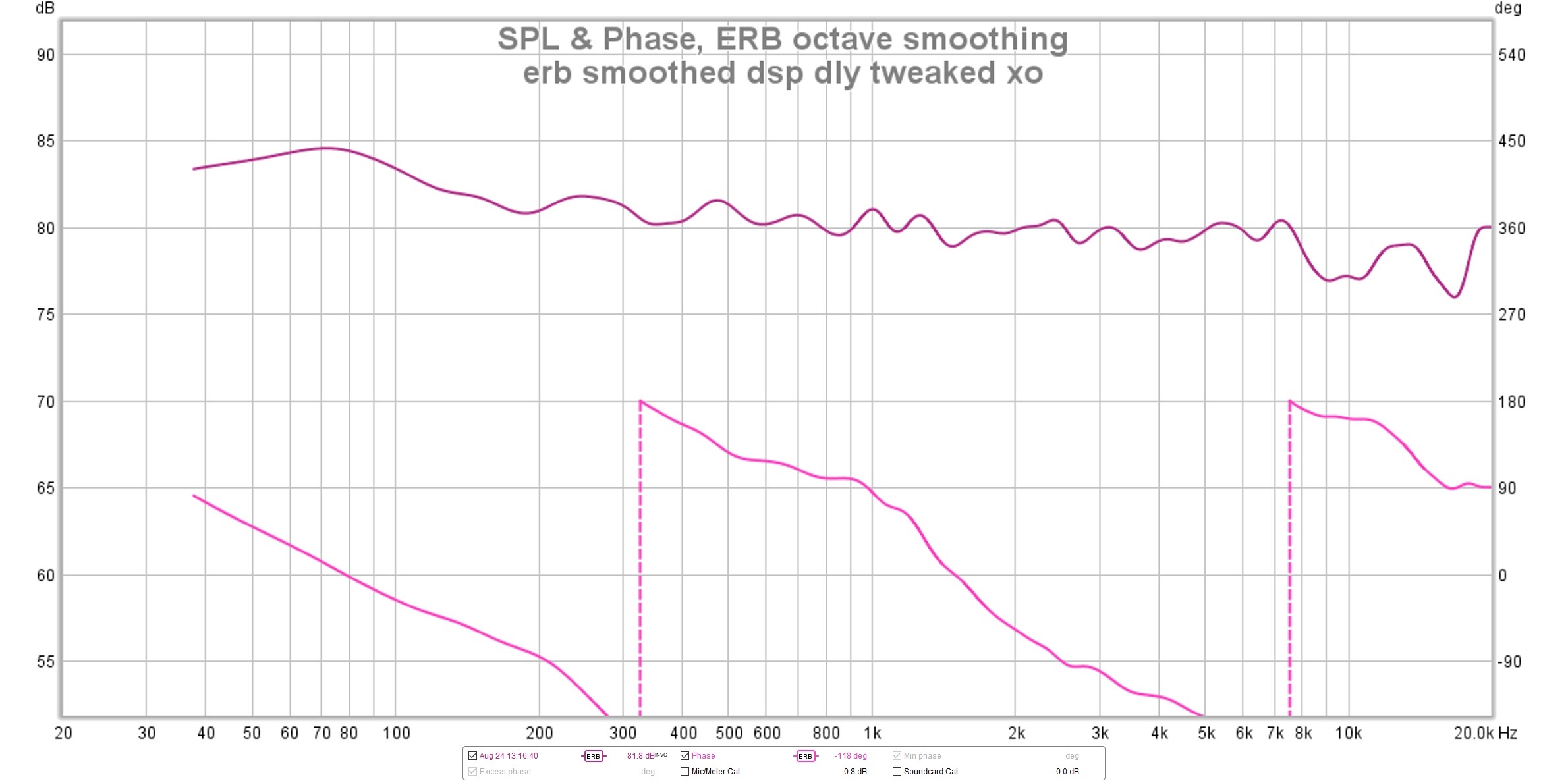
(edit: notice I have a phase flip at/near 300 hz. APL tells me this is non-min phase as you might expect given the floor reflection apparent there)
I like my bass a little hot but I can see I need to pull down the high end a little more. I haven't really tried to voice these speakers but I've done enough to realize it makes a difference.
Here is the APL_TDA display of harmonic distortion:
The 2nd bass unit will help down at the very low end.
Attachments


Thanks, Jack! These all showed up this time (as opposed to white boxes, like others have noted).
And great progress. Hopefully you'll enjoy them off the test stand soon? 😀
And great progress. Hopefully you'll enjoy them off the test stand soon? 😀
Thanks reposting now can see below what wesayso's comment "looking pretty sweet" was all about : )
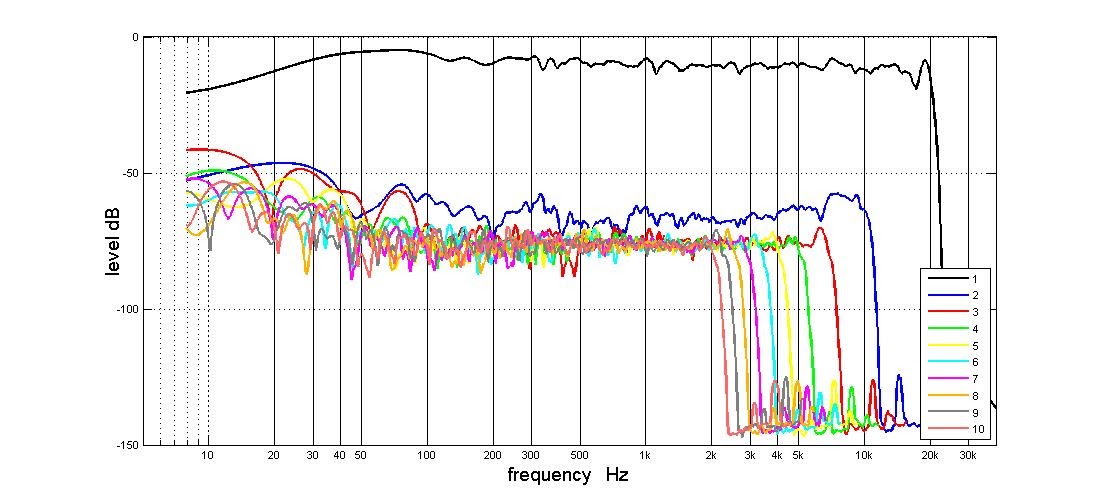
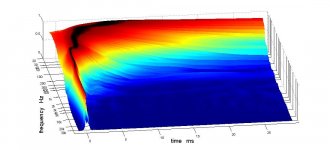
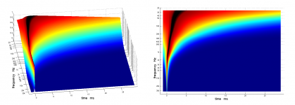
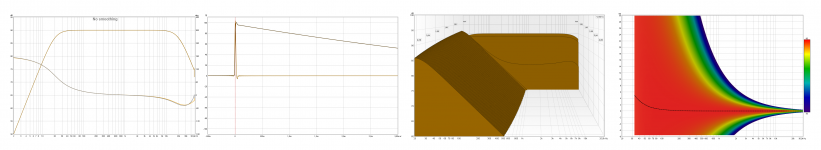
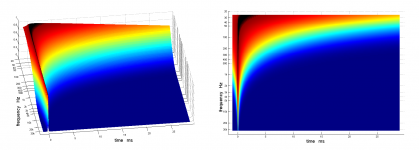
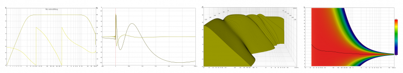
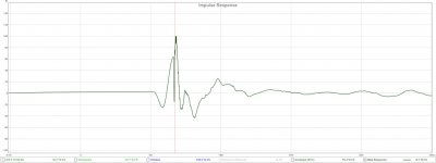
For fun created in Rephase a textbook IRR domain IR for close as can guess to your real XO's band passes which here set as 225Hz BW2 slope and 950Hz BW4 slope, system stop-bands is set 20Hz-20Khz BW2 slopes.
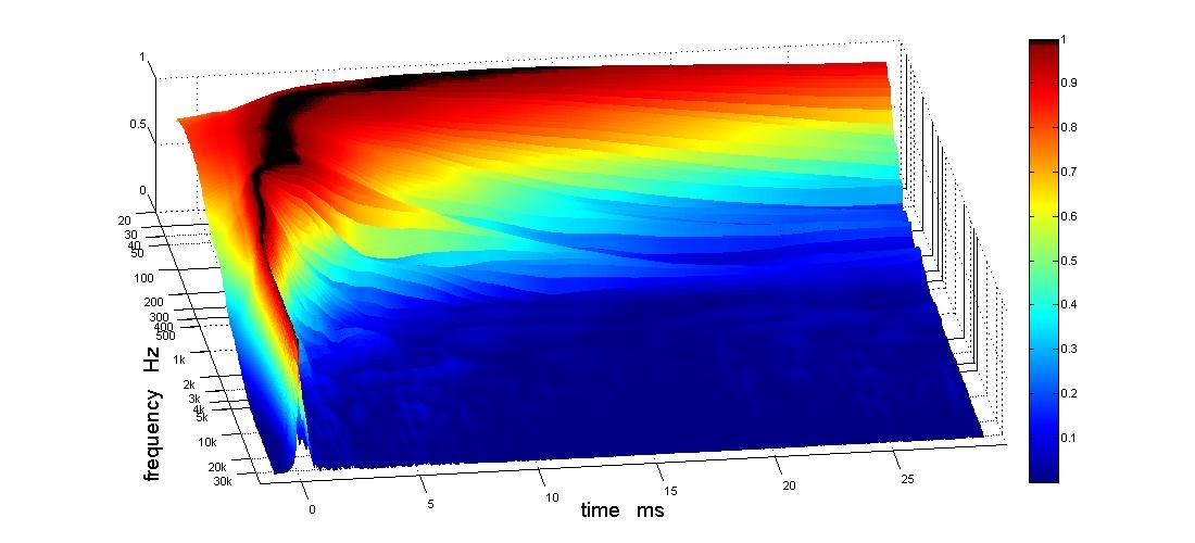
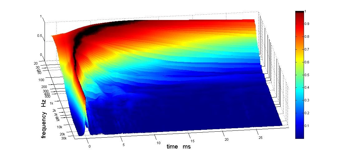
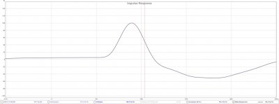
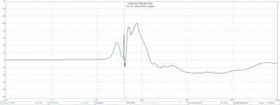
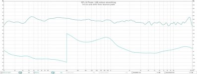
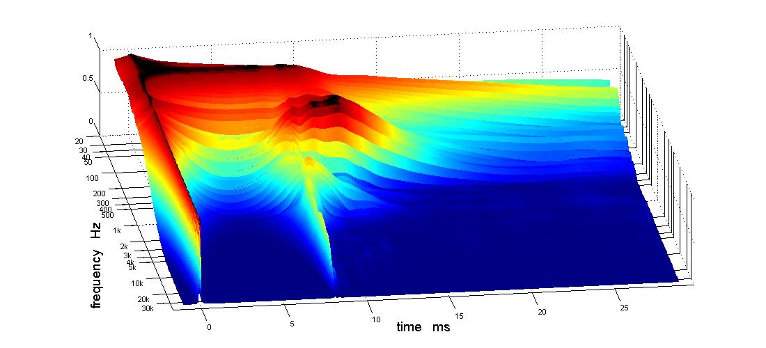
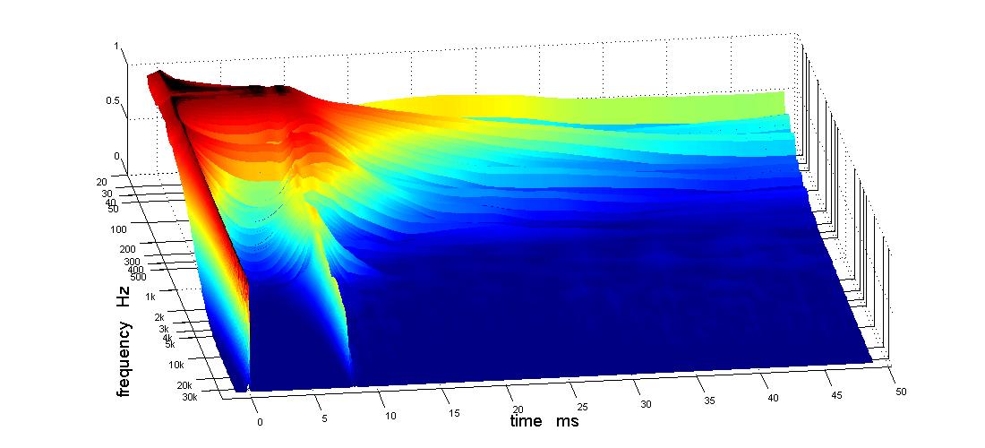
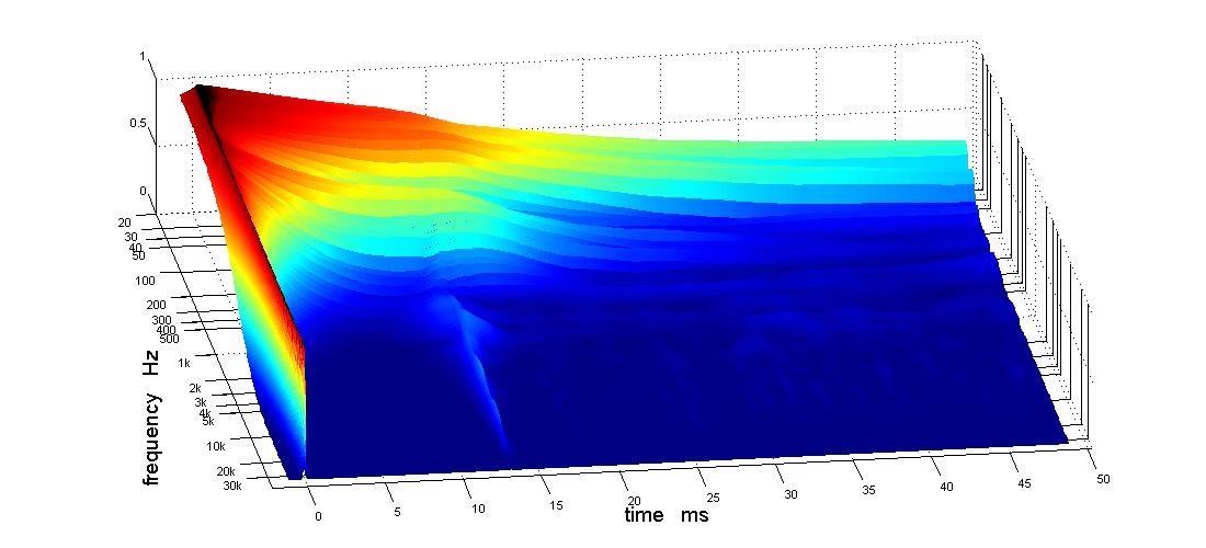
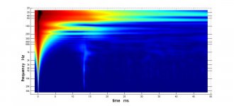
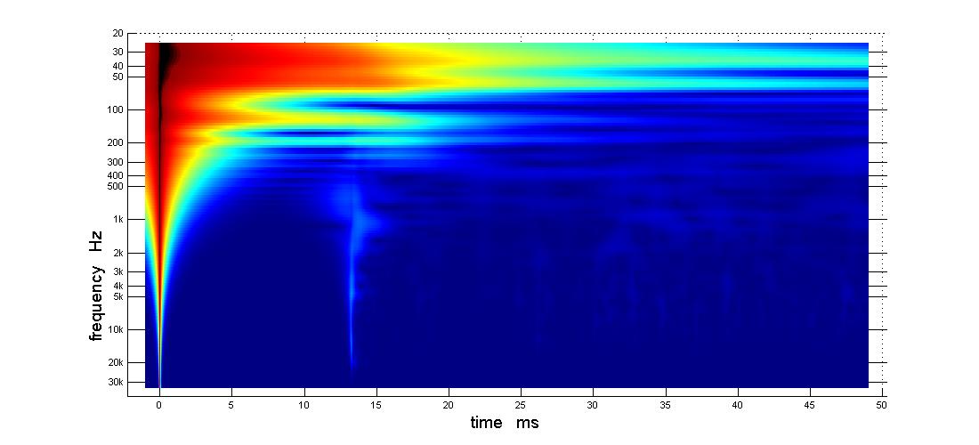
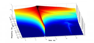
When IR is imported into APL_TDA_v010 (forgot to upgrade lately 🙂) it looks like picture-1. Same IR Imported to REW looks like picture-2, and if as talked about earlier you neutralize IRR XO points with DSP power to end up in a clean IRR domain 20Hz-20kHz picture-3 and 4 show these improved waterfall mids.
For fun created in Rephase a textbook IRR domain IR for close as can guess to your real XO's band passes which here set as 225Hz BW2 slope and 950Hz BW4 slope, system stop-bands is set 20Hz-20Khz BW2 slopes.
When IR is imported into APL_TDA_v010 (forgot to upgrade lately 🙂) it looks like picture-1. Same IR Imported to REW looks like picture-2, and if as talked about earlier you neutralize IRR XO points with DSP power to end up in a clean IRR domain 20Hz-20kHz picture-3 and 4 show these improved waterfall mids.
Attachments
Last edited:
Thanks reposting now can see below what wesayso's comment "looking pretty sweet" was all about : )
For fun created in Rephase a textbook IRR domain IR for close as can guess to your real XO's band passes which here set as 225Hz BW2 slope and 950Hz BW4 slope, system stop-bands is set 20Hz-20Khz BW2 slopes.
When IR is imported into APL_TDA_v010 (forgot to upgrade lately 🙂) it looks like picture-1. Same IR Imported to REW looks like picture-2, and if as talked about earlier you neutralize IRR XO points with DSP power to end up in a clean IRR domain 20Hz-20kHz picture-3 and 4 show these improved waterfall mids.
I can't wait, assuming that it sounds as good as those pictures look.
I've got an OpenDRC on the shelf and downloaded RePhase. OTOH forced to wait - for time to play with it plus a new USB hub behind which the OS will be able to find my amp, soundcard, usb to toslink output, and two minDSP units. Good luck with that he says...
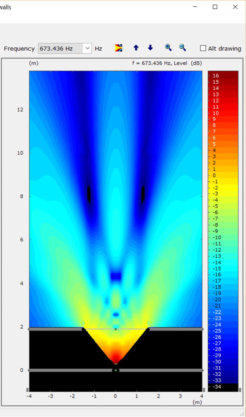
Well, while I was waiting for various things to arrive, I distracted myself by rereading the LeCleach thread, which put me onto AxiDriver. I realized that AxiDriver could simulate my corner horn both with and without a secondary flare. Here is a picture from that effort. Given my intended use for home theater/TV as well as music, this gives new meaning to the term "rabbit ears"
Attachments

Was that a bat or a rabbit? It looks more like a bat in the inline image, which was squashed vertically by the software. I"m not sure why its doing this and yes, it did it again, so click the images to see what they really look like!
My axidriver simulations convince me my horns want to be listened to as directly on axis as possible, where the HF beam is the widest. Rotating them about 11 degrees away from the front wall seems optimal for my listening geometry. That is only 4" or so distance between the inside edge of the bass bin and the front wall. That will also angle the contralateral radiation away from the front wall and TV stand that would otherwise (and might still) be a reflection source....
Anyway, I've finally gotten some paint on the horn so it won't be long before I can bring them inside and try them in a more benign environment. I did the entire horn with the wall color (which is more yellow than white but the picture was taken under a flourescent light) and didn't like it, then painted the lower horizontal flare a flat black. I think that is going to do it.
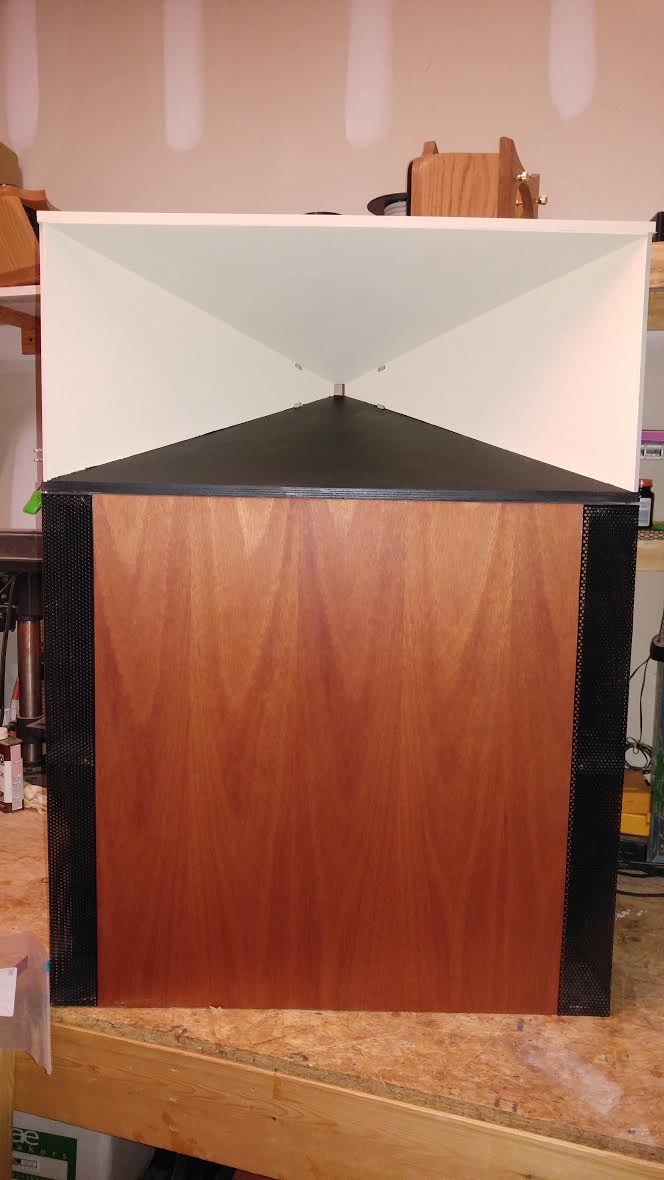
If/when I stack a 2nd bass bin on top, I will paint the upper horizontal flare black also.

My axidriver simulations convince me my horns want to be listened to as directly on axis as possible, where the HF beam is the widest. Rotating them about 11 degrees away from the front wall seems optimal for my listening geometry. That is only 4" or so distance between the inside edge of the bass bin and the front wall. That will also angle the contralateral radiation away from the front wall and TV stand that would otherwise (and might still) be a reflection source....
Anyway, I've finally gotten some paint on the horn so it won't be long before I can bring them inside and try them in a more benign environment. I did the entire horn with the wall color (which is more yellow than white but the picture was taken under a flourescent light) and didn't like it, then painted the lower horizontal flare a flat black. I think that is going to do it.
If/when I stack a 2nd bass bin on top, I will paint the upper horizontal flare black also.
Attachments


Its been a while but I've emerged from driver hell with the 2nd horn completed and a refined cross over for it.
I had a working test bench and made the mistake of trying to improve it. The single ended line out outputs from my sound card were noisy so I bought a $10 USB to Toslink adapter to go digital into my DSP. This worked awesomely for playing music but its ASIO grabbed the input and I couldn't use my sound card for measurements because the VIA driver for the Toslink adapter wouldn't let go of the input stream without at least a restart.
I needed more USB inputs and so I bought a USB hub. I found that almost nothing of mine audio works reliably through a USB hub, except that problematic Toslink adapter. The hub turned out to be a terrible idea because it allowed me to connect two MiniDSPs at once - the original 4x10 that does the IIR XO and my new OpenDRC which was to add FIR capability. The problem is that the MiniDSP software doesn't work with two of their DSP devices connected and the symptoms are confusing. It took a while to figure that out. Along the way, I bought a new sound card to get balanced line outputs and up to date driver support. It took another while to get the driver issues sorted out. I had to run an audio mixer program to get control of the sample rate. Without that running, Windows keeps defaulting it back to 44.1 Khz.
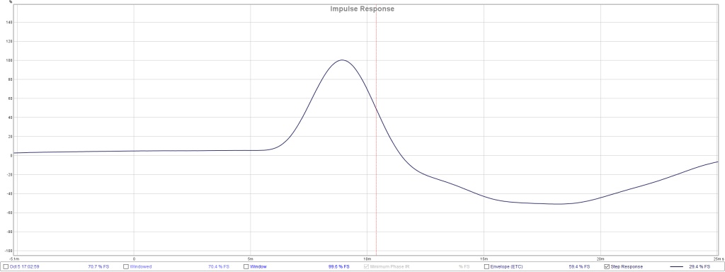
I finally got past all that yesterday and got my best DSP IIR XO yet for these Synergy horns. I first flattened the frequency of each driver individually, then added the XO low pass and high pass filters, then added DSP delays for precise time alignment, using REW IR with timing reference loopback to judge alignment. I went around this loop a couple of times and ended up with this IR:
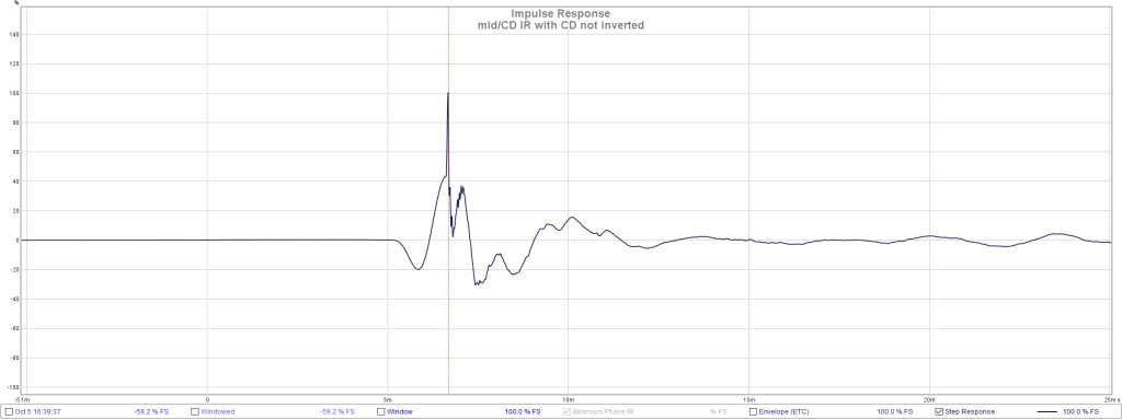
a nice narrow CD impulse centered within a broader pulse from the mids.
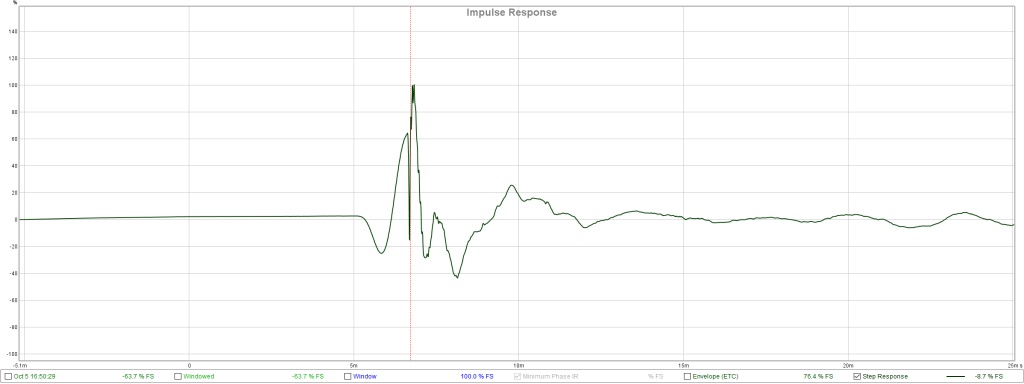
Looking at it in the frequency domain, I saw a sharp null almost right at the intended XO. I could have clicked "invert" on the CD output and been done but in the interests of my own education, I tried to do the equivalent with digital all pass filters. Eventually I went back to electrically inverted CD, added a few input PEQs for the worst remaining bumps and called it done.
This is the fnal/latest IR for the CD plus mids:
Now it was time to bring in the woofer. I had made things simpler for myself by doing a 2 way XO for the CD/mids and so had to do another 2 way XO for the Synergy horn with the bass bin it sits on. I moved the measurement mic out to 2m so the path length difference between synergy and bass bin was more representative of the actual listening position. I didn't dare go out to the full 3.5 m for fear of reflection and room mode issues.
The woofer is a sealed slot loaded AE TD15H. Its natural response starts rolling off around 55 Hz. I'm using a linkwitz transform with about 10 db of gain to lift the low end. It has a really fat impulse response. Part of that is no doubt due to its lower bandwidth but as you might expect there are some room modes in play. The woofer impulse:
I decided to place the Synergy impulse on the leading edge of the woofer impulse. This is what resulted, I don't know quite what to make of it:
Here is the corresponding nicely flat REW frequency response:
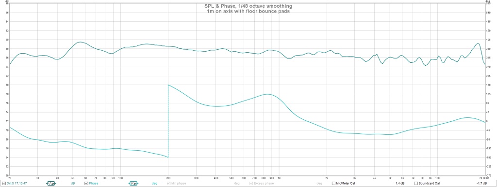
Note those are 2 db steps between grid lines.
I have some interesting APL TDA graphs to show but this post is already too long.
Jack
I had a working test bench and made the mistake of trying to improve it. The single ended line out outputs from my sound card were noisy so I bought a $10 USB to Toslink adapter to go digital into my DSP. This worked awesomely for playing music but its ASIO grabbed the input and I couldn't use my sound card for measurements because the VIA driver for the Toslink adapter wouldn't let go of the input stream without at least a restart.
I needed more USB inputs and so I bought a USB hub. I found that almost nothing of mine audio works reliably through a USB hub, except that problematic Toslink adapter. The hub turned out to be a terrible idea because it allowed me to connect two MiniDSPs at once - the original 4x10 that does the IIR XO and my new OpenDRC which was to add FIR capability. The problem is that the MiniDSP software doesn't work with two of their DSP devices connected and the symptoms are confusing. It took a while to figure that out. Along the way, I bought a new sound card to get balanced line outputs and up to date driver support. It took another while to get the driver issues sorted out. I had to run an audio mixer program to get control of the sample rate. Without that running, Windows keeps defaulting it back to 44.1 Khz.
I finally got past all that yesterday and got my best DSP IIR XO yet for these Synergy horns. I first flattened the frequency of each driver individually, then added the XO low pass and high pass filters, then added DSP delays for precise time alignment, using REW IR with timing reference loopback to judge alignment. I went around this loop a couple of times and ended up with this IR:
a nice narrow CD impulse centered within a broader pulse from the mids.
Looking at it in the frequency domain, I saw a sharp null almost right at the intended XO. I could have clicked "invert" on the CD output and been done but in the interests of my own education, I tried to do the equivalent with digital all pass filters. Eventually I went back to electrically inverted CD, added a few input PEQs for the worst remaining bumps and called it done.
This is the fnal/latest IR for the CD plus mids:
Now it was time to bring in the woofer. I had made things simpler for myself by doing a 2 way XO for the CD/mids and so had to do another 2 way XO for the Synergy horn with the bass bin it sits on. I moved the measurement mic out to 2m so the path length difference between synergy and bass bin was more representative of the actual listening position. I didn't dare go out to the full 3.5 m for fear of reflection and room mode issues.
The woofer is a sealed slot loaded AE TD15H. Its natural response starts rolling off around 55 Hz. I'm using a linkwitz transform with about 10 db of gain to lift the low end. It has a really fat impulse response. Part of that is no doubt due to its lower bandwidth but as you might expect there are some room modes in play. The woofer impulse:
I decided to place the Synergy impulse on the leading edge of the woofer impulse. This is what resulted, I don't know quite what to make of it:
Here is the corresponding nicely flat REW frequency response:
Note those are 2 db steps between grid lines.
I have some interesting APL TDA graphs to show but this post is already too long.
Jack
Attachments
I was still having driver issues running APL_TDA so I did that XO development without it. The driver issues resolved about the same time the XO came together.
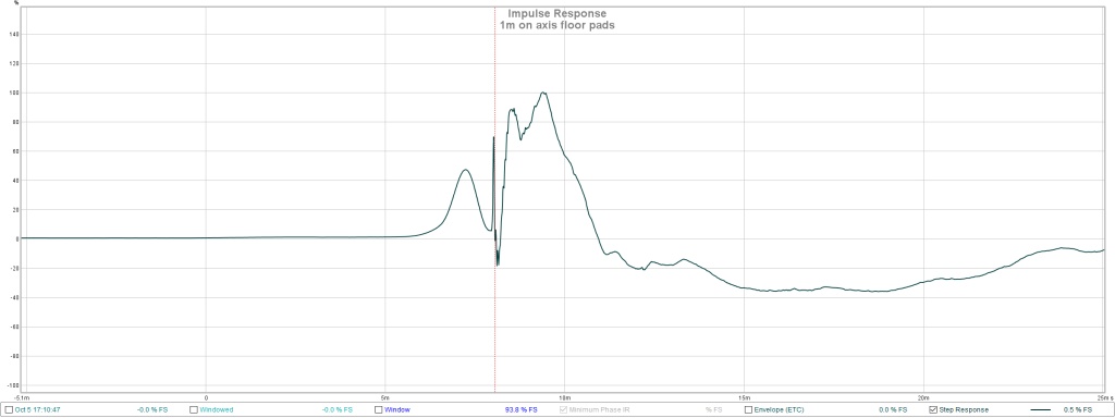
Here is an APL_TDA plot of the response with the speaker sitting on the garage floor without benefit of any absorbers.
The image confirms time alignment and shows some floor bounce reflections which clean up somewhat when I put my usual floor pads in place:
There is a "ghost" reflection out at 8 ms or 9' that extends into the HF. I spent some time padding various surfaces but I never did discover its source.
Putting that aside, I moved the mic out to my intended in room listening distance and angle and got the following plot. This is about 3m and perhaps 20 degrees off axis.
I don't what to say about the above. Its almost too good to be true. The 2D image is more revealing but I can't insert it. Let me continue in the next post.
Jack
Attachments


You might want to check both sides of the graph just to be sure. As your Step response has a positive swing before the HF peak you'd want to see a bit more detail what's happening on both sides. Also make a new FR plot at this position. Phase should be quite flat to get an APL plot that looks like that. Remember the APL plot is normalising the data and you'd need to look at the AFR and DFR plots to see the complete picture.
I'm a bit surprised there isn't any roll off visible on the woofers in the low end.
For a more natural sound I let the woofer roll off alone in my FIR compensation. Do you use IIR filters to boost the low end?

I'm a bit surprised there isn't any roll off visible on the woofers in the low end.
For a more natural sound I let the woofer roll off alone in my FIR compensation. Do you use IIR filters to boost the low end?
Trying again with that 2D image:
That ghost is still there at the same delay but fainter. How can it be due to the horn? An 8 ms delay corresponds to 9' and the horn is only about 16" deep. The ceiling is 11' high and the horn apex is 32" off the floor.
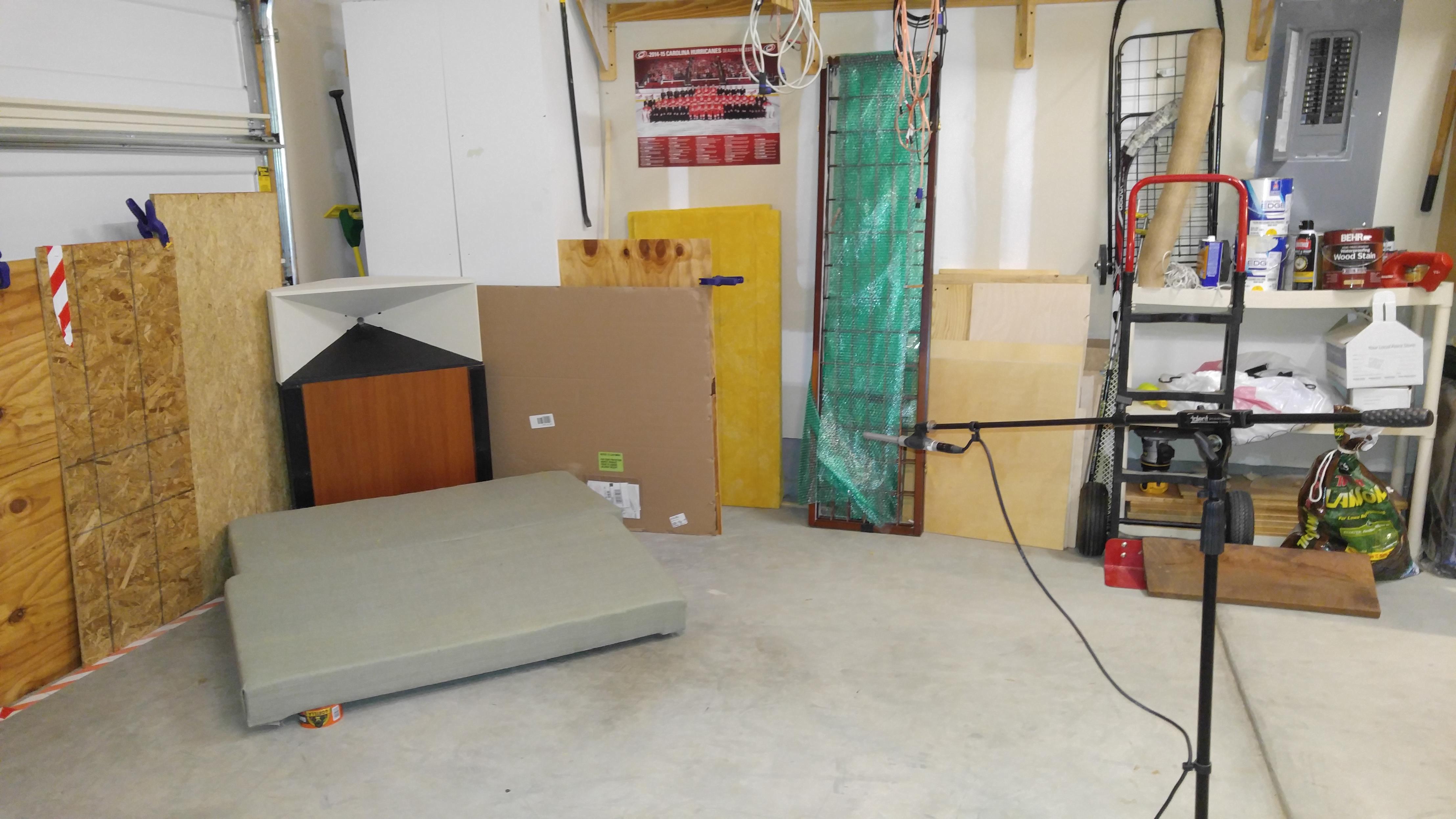
Here is a shot of my measurement setup. Does anybody see anything suspicious there? Those objects along the far wall, perhaps?
This is with just an IIR XO. It will be interesting to see what benefits I get from bringing the OpenDRC into the picture.
That ghost is still there at the same delay but fainter. How can it be due to the horn? An 8 ms delay corresponds to 9' and the horn is only about 16" deep. The ceiling is 11' high and the horn apex is 32" off the floor.
Here is a shot of my measurement setup. Does anybody see anything suspicious there? Those objects along the far wall, perhaps?
This is with just an IIR XO. It will be interesting to see what benefits I get from bringing the OpenDRC into the picture.
Attachments


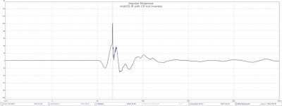
I'm having a hard time reconciling your IR and phase response plot with the APL_TDA plots. The phase looks like it's nearly inverted at 1kHz, the IR doesn't look much like a pulse, but the APL shows linear phase? Are you not using the FIR to flatten the phase, or am I misreading one or both of these posts? I'd expect the IR to be something like this
Attachments
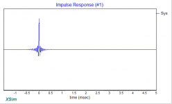
The legend under the graph shows we are looking at a STEP response, not an IR. The later APL plots are taken at a different point than the FR graph posted earlier. Until we see the actual frequency response belonging to the APL plot we don't see the complete picture.
I was looking at the plots the same way as you, Bill, 180 degree phase swing at 200 Hz should also show up in an APL plot 🙂. What are we looking at in REW? Is it using a frequency dependent window? Is it a 500 ms window smoothed.
The two don't match up.
Anything behind the mic that can reflect back to it? As it moves with the mic position and is a very clear copy you should be able to find a direction with moving around one of those matrasses? It should also show up in the IR.
I still have a hard time seeing how this straight line can be all the way down with only using IIR filters in the APL plot with the REW plots showing a different story.
Last edited:
You might want to check both sides of the graph just to be sure. As your Step response has a positive swing before the HF peak you'd want to see a bit more detail what's happening on both sides. Also make a new FR plot at this position. Phase should be quite flat to get an APL plot that looks like that. Remember the APL plot is normalising the data and you'd need to look at the AFR and DFR plots to see the complete picture.
I'm a bit surprised there isn't any roll off visible on the woofers in the low end.
For a more natural sound I let the woofer roll off alone in my FIR compensation. Do you use IIR filters to boost the low end?
Hi Wesayso:
I appreciate your comments as I'm just feeling my way through this stuff for at most the second time.
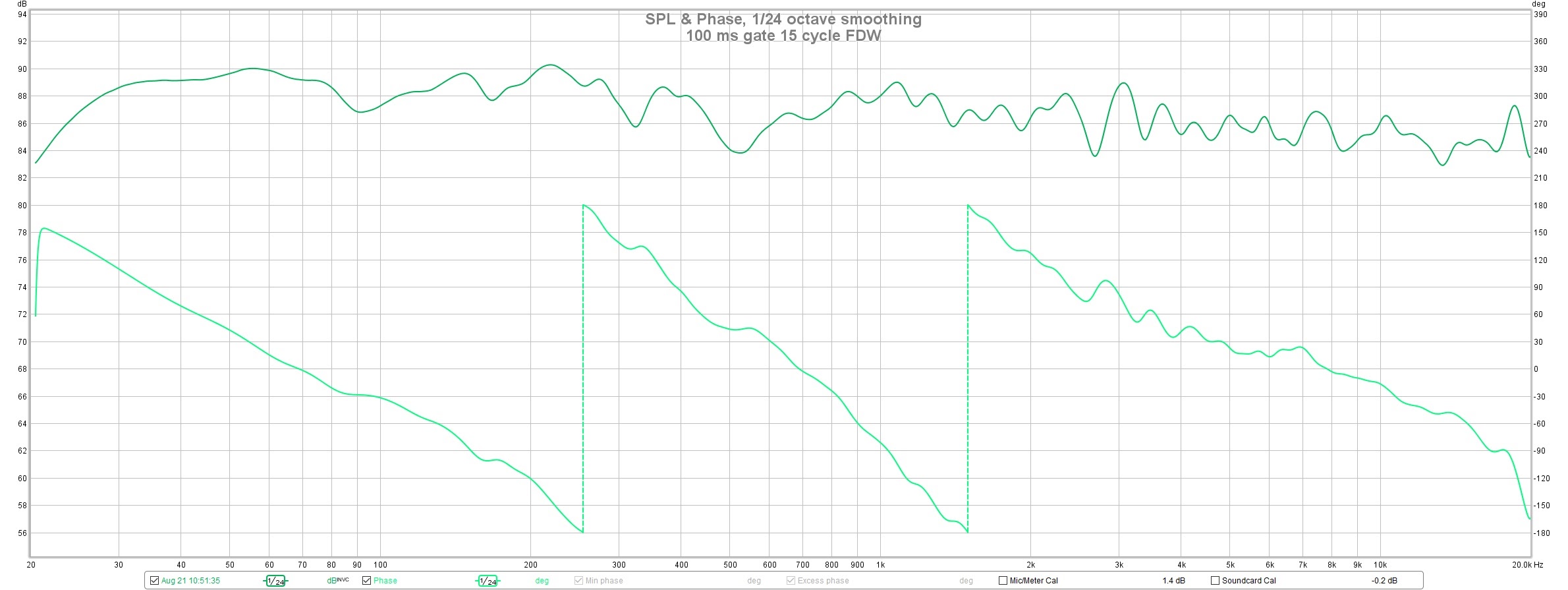
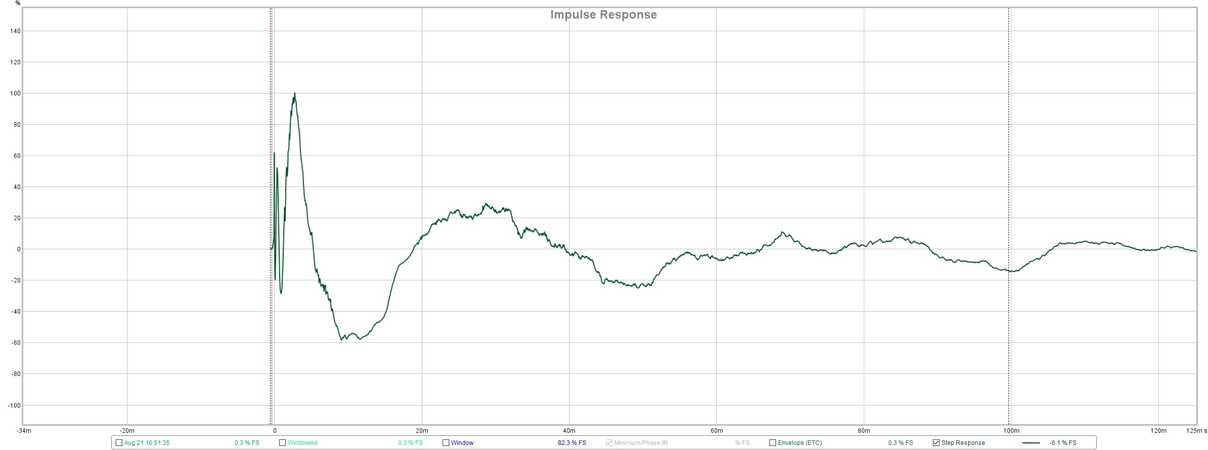
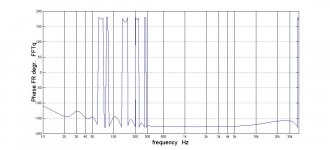
I find that IR plot fairly confusing myself in the way it initially swings in the wrong direction. You can see the phase in a REW FR plot a couple of post back. Its fairly flat, except for a phase flip at 200 hz, just about right on the nominal woofer XO.
I've got a Linkwitz transform on the woofer; otherwise it would be rolling off below 55 Hz or so. I have some subs up in the room that should remove the need for it. I expected flat to 20 Hz with the LT but I can't seem to pressurize the garage any more than what you see in the plots. That is a thin, leaky garage door.
Here is your look at the other side:
Attachments
I'm having a hard time reconciling your IR and phase response plot with the APL_TDA plots. The phase looks like it's nearly inverted at 1kHz, the IR doesn't look much like a pulse, but the APL shows linear phase? Are you not using the FIR to flatten the phase, or am I misreading one or both of these posts? I'd expect the IR to be something like this
I expected, or at least hoped, it to look like that also; that is why I posted in such detail. Is it a step or an impulse response? All I know is that I pressed "impulse" button on the REW screen.
I'm not using FIR at all. The APL isn't showing linear phase so much as nearly constant group delay. The APL phase plot shows multiple phase flips between 50 and 300 Hz but quite flat above 300 Hz.
Attachments
- Home
- Loudspeakers
- Multi-Way
- My Synergy Corner Horn and Bass Bins