If one must accept a reflection, wouldn't it be better that it be less frequency dependent?The context of my point was that these late arriving reflections would not be colored due to waist banding of the horn pattern
The exception might be that reflections can be somewhat more benign by the 600Hz you mention, and below. Down there the simple response variations can become the primary concern.
Of course. My point was that they would be less frequency dependent. The rays that reach my ear by reflection off the opposite side wall are about the same distance off axis as those that reach my ears directly, but on the opposite side of the axis. Thus the EQ I do to flatten the direct sound, will also flatten this indirect sound.
Consider sound that hits a near side wall from the horn. These rays will be near 45 degrees off axis, where the frequency varies considerably more than in the inner half of the Vee. But these sounds never reach my ears, at least not after a single reflection.
I don't know how much absorption I'll eventually place in the room. Will you forgive me if I say, I'm going to play that by ear?
These posts weren't intended to address absorption or the need for it. I started out this chain of thought trying to estimate how much the observed midband narrowing will hurt my eventual system performance after equalization. It was an AHA moment for me to realize I should and could check which angles on the horn corresponded to the first reflections.
When I tried placing a ceiling batt over my ceiling reflection points I discovered there was an emphasis around what seemed to be the low/middle kHz region. I had been equalising around this without realising. This was a clear improvement. I could speculate as to why the range was what it was, don't know if that would be the point.I don't know how much absorption I'll eventually place in the room. Will you forgive me if I say, I'm going to play that by ear?
I changed from axissymmetrical to elliptical waveguides and found the benefit to the ceiling reflection was part way between the former, and the former with the absorber. Considering the technical difficulty in transitioning a round exit compression driver to elliptical, the difficulty in building it (and doing it accurately), and the apparent lack of point in my situation I decided not to go that way.
But yes, the point is try it and see.
Thanks, AllenB, it helps to know that ceiling treatment provided an audible improvement, despite no doubt sounding good without it. I expect to add ceiling treatment at some point. Also, I belatedly realize that there may well be some benefit to attenuating/absorbing a first reflection, if it is too strong.
back to the build
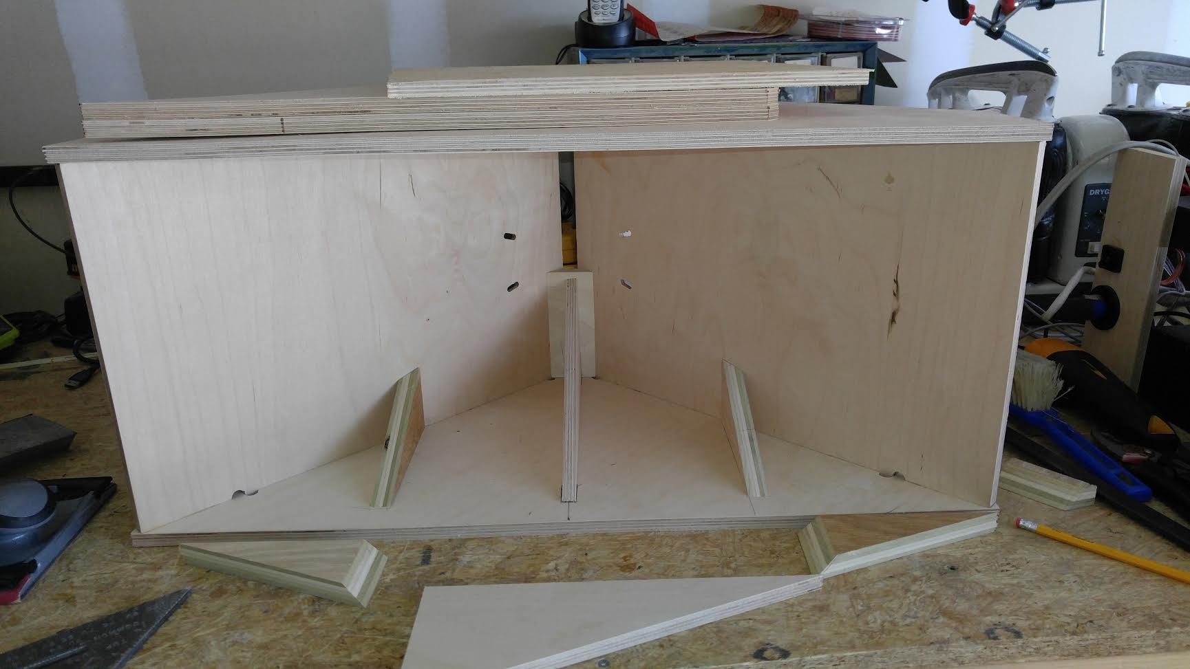
I just glued to top and bottom plates to the vertical flares to which the midchambers had already been attached

The metal brackets simply confirm it is plumb vertically.
Here is the view from the back:

Next it gets serious because I have to cut the bevels on the horizontal flares and trim corner plugs to fill in the gap between the two vertical flares, leaving an opening for the H flares and CD. The corner plugs catch wood screws that come in from the back and hold the CD mounting plate in place.
But for now, I'm off to the ice rink!
I just glued to top and bottom plates to the vertical flares to which the midchambers had already been attached
The metal brackets simply confirm it is plumb vertically.
Here is the view from the back:
Next it gets serious because I have to cut the bevels on the horizontal flares and trim corner plugs to fill in the gap between the two vertical flares, leaving an opening for the H flares and CD. The corner plugs catch wood screws that come in from the back and hold the CD mounting plate in place.
But for now, I'm off to the ice rink!
Getting ready to cut H flare bevels
My bevel angle jig is a simple as you can get: a piece of plywood with a 3/4" wide strip of wood glued and screwed to the back to ride in the table saw groove and a piece of angle aluminum to use as a ledger.

I'm usually cutting bevels on a piece cut to size by CNC. I first butt the fence up against the jig with the edge I want to cut against the fence. I then rotate the aluminum ledger flush to the piece and screw it in place. Eventually I might make swiss cheese of my jig but at the rate I'm going I'm not worried about it.
This time I want to make smaller clones of the first piece to brace my horizontal flares. I slide the fence out of the way. Put the scrap of plywood on the ledger and simply cut it off. I just hold it place with my hand for the cut. No, I haven't lost any fingers yet.

I flip the piece over and do it again. Then the take the remainder over to my miter saw and cut off both ends. After trimming and another miter cut on each piece, I have 4 braces.
Here is one set of braces laid out on the bottom plate of the horn:
My bevel angle jig is a simple as you can get: a piece of plywood with a 3/4" wide strip of wood glued and screwed to the back to ride in the table saw groove and a piece of angle aluminum to use as a ledger.
I'm usually cutting bevels on a piece cut to size by CNC. I first butt the fence up against the jig with the edge I want to cut against the fence. I then rotate the aluminum ledger flush to the piece and screw it in place. Eventually I might make swiss cheese of my jig but at the rate I'm going I'm not worried about it.
This time I want to make smaller clones of the first piece to brace my horizontal flares. I slide the fence out of the way. Put the scrap of plywood on the ledger and simply cut it off. I just hold it place with my hand for the cut. No, I haven't lost any fingers yet.
I flip the piece over and do it again. Then the take the remainder over to my miter saw and cut off both ends. After trimming and another miter cut on each piece, I have 4 braces.
Here is one set of braces laid out on the bottom plate of the horn:
Cutting the H flare bevels
This morning I got back to the build. Even though I used BWaslo's spreadsheet to get the horn dimensions, I prefer to have Sketchup tell me what angles to cut.

I have to cut both the curner plug and one edge of the flare at 22.5. First thing is set the angle on the saw.

Here is the corner plug on the table saw but I actually cut that angle on my miter saw. This is a sanity check.

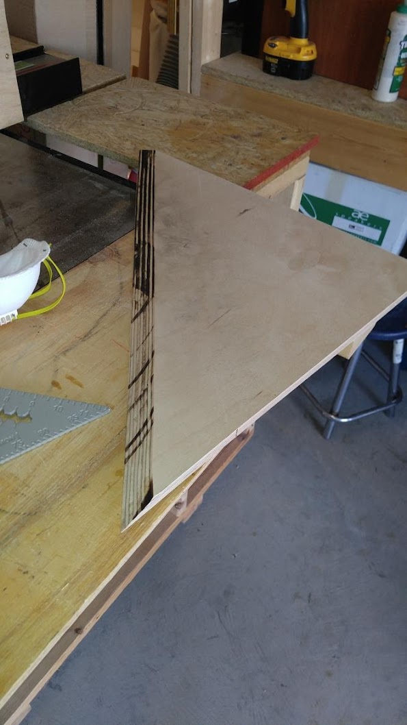
To cut the complementary angle on the H flare, I have to hold it at orthogonal to the table saw top. My vertical jig is just two pieces of plywood that fit snugly and squarely on my robust fence. Here is the piece at the end of the cut. Before I cut it, I made sure the insert around the blade was flush.

But I went too slow and got some burn on the edge where it doesn't show. The edge itself is nice and clean and right on point.
This morning I got back to the build. Even though I used BWaslo's spreadsheet to get the horn dimensions, I prefer to have Sketchup tell me what angles to cut.
I have to cut both the curner plug and one edge of the flare at 22.5. First thing is set the angle on the saw.
Here is the corner plug on the table saw but I actually cut that angle on my miter saw. This is a sanity check.
To cut the complementary angle on the H flare, I have to hold it at orthogonal to the table saw top. My vertical jig is just two pieces of plywood that fit snugly and squarely on my robust fence. Here is the piece at the end of the cut. Before I cut it, I made sure the insert around the blade was flush.
But I went too slow and got some burn on the edge where it doesn't show. The edge itself is nice and clean and right on point.
continuing
here is a test fit. It doesn't lfit well but I haven't cut the angles on the sides yet.

When I set the jig for the side bevels, I was comforted to find screw holes already in place for the ledger from the first build

This is my final dry fit. You can't see it but the front edge hangs over the bottom plate about 1/32". I'll sand that off. That gauge in the H Flare is disappointing but doesn't really matter because I'm just painting these pieces.

Now onto gluing. First is the corner plug, then lunch...

here is a test fit. It doesn't lfit well but I haven't cut the angles on the sides yet.
When I set the jig for the side bevels, I was comforted to find screw holes already in place for the ledger from the first build
This is my final dry fit. You can't see it but the front edge hangs over the bottom plate about 1/32". I'll sand that off. That gauge in the H Flare is disappointing but doesn't really matter because I'm just painting these pieces.
Now onto gluing. First is the corner plug, then lunch...
Thank you for posting the assembly/cut shots. I'm starting down the synergy path and it's nice to see these examples.
Nice work
thanks, but I didn't show closeups of the first one, which didn't come out quite so good. But a little bondo in the joint and it was ready to paint. In fact, its still ready to paint; haven't done that yet.
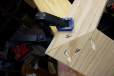
Had a little panic yesterday when my 20 year old brad nailer failed in the middle of securing one of the H Flare braces. I worked around that and then got a new one and continued. This morning I glued and clamped the first H flare.
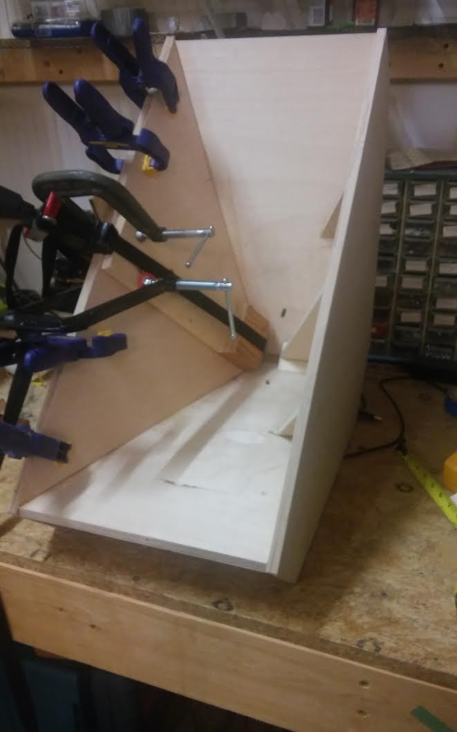
I debated whether to use titebond or PL-51 but when my partially used PL-51 tube saved from the first build turned out to be hardened the decision was made for me. I got a little squeeze out to confirm fit but most, if there was any more, occurred under the flare where I can't see it. That is one of the problems with building in this order. The other one was how to clamp the throat end of the flare. The benefit though was the flares are held in precise alignment; all I have to do is apply pressure.
I had a light weight cable clamp ready to pull the back of the flare in tight. Got that set up and then put braces all along the front edge, just to be sure. Parallel edge clamps don't work on the angled edge but C-clamps do.
In 2 hours or so, I can do the other flare.
back to the crossover
I'm putting the 2nd horn aside for now and going back to the crossover work on the first one.
Its actually time for me to decide whether to take my own advice and use bondo to do the final shaping on my frustrums or choose one of the new options that have been mentioned in BWaslo's thread 🙂 The easiest thing for me to do would be use some of that modelling clay that I have for smoothing the throat - but I'm afraid its grip on the horn wall might be an issue long term.
I also want to paint this horn before I mount drivers on it and I'm still not sure how I want to do that. Can it be done by brush or do I need to buy a sprayer and learn how to use it?
I'm using a MiniDSP 4x10 for my XO. My plan is to see how close I can get the phase to flat with that and then include my OpenDRC-DI for linearization and room correction.
I've done a couple of XOs already and, while they sounded good, even great, measurements didn't show the predicted flat frequency responses. What was I doing wrong? Well, either I had bad measurements, wasn't able to gate/window reflections out of my indoor measurements or I didn't get the drivers time aligned or some or all of the above.
While I was pondering this, I got an APL_TDA license and was able to see at a glance what the problem was. Yes the problem was time alignment but APL_TDA is equally good at showing what room modes and boundaries are doing to a response as it at showing driver time alignment issues.
Before I go on, let me say that as part of the consideration for the APL_TDA license I will be doing a review of the tool.
Using APL-TDA to check driver time alignment
The first XO I really listened to on this system was a Harsch, consistent with my intention to see how close to flat I could get the phase without resort to FIR.
Here is the measured frequency response, both raw and 4 cycle FDW overlaid.

and here is its measured impulse response:

The frequency response is nowhere near flat but after using iTunes equalizer I quickly became enthused with it. The IR clearly has issues but I'm not an experienced reader of these kind of tea leaves.
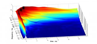
The APL_TDA display is easier to read. APL_TDA creates a 3d display of linear intensity vs time and frequency. On it one can see time alignment, resonances and reflections at a glance. (google APL_TDA for info).
Here is the 3d chart for this XO. I got this not by measuring in APL_TDA but by exporting and importing an IR from a REW measurement.

The corresponding 2D display isn't as pretty but can be easier to read
The horizontal red streaks are room resonances. Clearly I have time alignment issues between the 20 hz to 225 Hz woofer and the Synergy. There is a lot of group delay in the 200 to 1Khz covered by the Synergy mids. Much of this the group delay of the horn. I didn't know what to make of it at first by the step in delay at just under 1 Khz is CD/mid time alignment.
That time alignment error is painfully obvious in this "Delay Frequency Response" graph produced by APL_TDA
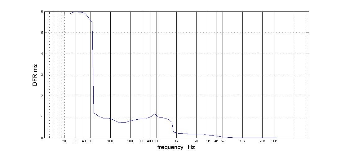
Note that the above is not a conventional group delay chart. TDA also produces this windowed GDR chart.
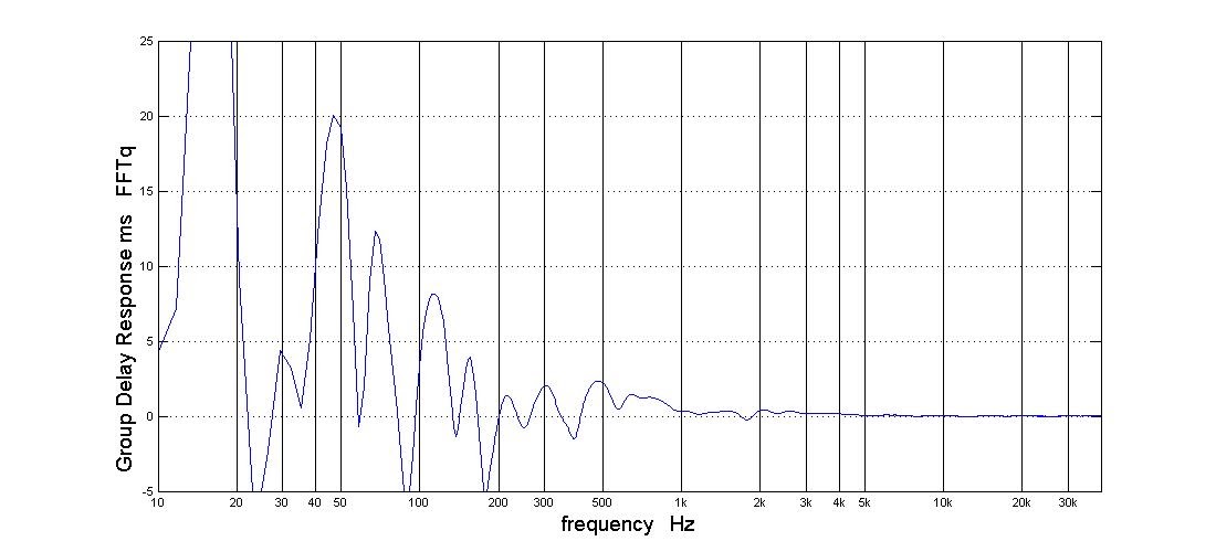
I can get very similar GD chart from REW by applying a 15 cycle FDW to the measurement. The delay and phase charts are discouraging but TDA can show me the group delay and phase response with min phase components subtracted.
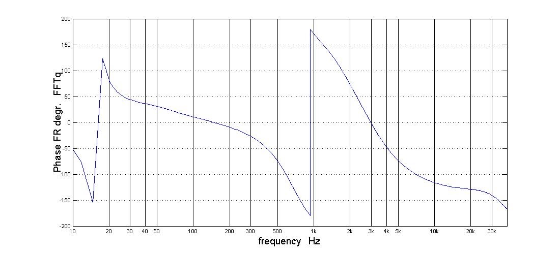
This min phase subtracted phase chart still has a phase flip at the mid/CD crossover. I will bet that that goes away whenI fix the time alignment.
The first XO I really listened to on this system was a Harsch, consistent with my intention to see how close to flat I could get the phase without resort to FIR.
Here is the measured frequency response, both raw and 4 cycle FDW overlaid.
and here is its measured impulse response:
The frequency response is nowhere near flat but after using iTunes equalizer I quickly became enthused with it. The IR clearly has issues but I'm not an experienced reader of these kind of tea leaves.
The APL_TDA display is easier to read. APL_TDA creates a 3d display of linear intensity vs time and frequency. On it one can see time alignment, resonances and reflections at a glance. (google APL_TDA for info).
Here is the 3d chart for this XO. I got this not by measuring in APL_TDA but by exporting and importing an IR from a REW measurement.
The corresponding 2D display isn't as pretty but can be easier to read
The horizontal red streaks are room resonances. Clearly I have time alignment issues between the 20 hz to 225 Hz woofer and the Synergy. There is a lot of group delay in the 200 to 1Khz covered by the Synergy mids. Much of this the group delay of the horn. I didn't know what to make of it at first by the step in delay at just under 1 Khz is CD/mid time alignment.
That time alignment error is painfully obvious in this "Delay Frequency Response" graph produced by APL_TDA
Note that the above is not a conventional group delay chart. TDA also produces this windowed GDR chart.
I can get very similar GD chart from REW by applying a 15 cycle FDW to the measurement. The delay and phase charts are discouraging but TDA can show me the group delay and phase response with min phase components subtracted.
This min phase subtracted phase chart still has a phase flip at the mid/CD crossover. I will bet that that goes away whenI fix the time alignment.
Last edited:
NC -
The more recent version of the SynergyCalc spreadsheet calculates intersection angles with a design that avoids having to cut any boards standing on end when going across the table saw. I had difficulty keeping enough accuracy with the boards propped up like that, and also it seemed kind of dangerous without a pretty complex fixture.
The later design structure also uses some additional alignment boards (see attached) for the first flare and a way to use pocket screws on the second flare so that the entire assembly can be dry-fit to check everything and can be assembled without tricky multimensional clamps, tape, or other means. There are photos of that in the SynergyCalc pdf files. http://libinst.com/SynergyCalc/Synergy%20Calc%20V5.pdf
Might make things a little easier (particularly if going for a wood-grain look with pre-veneered ply, where accuracy and adjustability are esential).
Attachments
If you're using an OpenDRC, why any need for time alignment? You can fix that all after the fact with its FIR features (and RePhase), get flat group delay without changing crossovers even.
Do you know how APL_TDA calculates that DFR graph? Seems like a neat feature.
Do you know how APL_TDA calculates that DFR graph? Seems like a neat feature.
NC -
The more recent version of the SynergyCalc spreadsheet calculates intersection angles with a design that avoids having to cut any boards standing on end when going across the table saw. I had difficulty keeping enough accuracy with the boards propped up like that, and also it seemed kind of dangerous without a pretty complex fixture.
The later design structure also uses some additional alignment boards (see attached) for the first flare and a way to use pocket screws on the second flare so that the entire assembly can be dry-fit to check everything and can be assembled without tricky multimensional clamps, tape, or other means. There are photos of that in the SynergyCalc pdf files. http://libinst.com/SynergyCalc/Synergy%20Calc%20V5.pdf
Might make things a little easier (particularly if going for a wood-grain look with pre-veneered ply, where accuracy and adjustability are esential).
If there is a best way to build these things, I don't know what it is yet. There are so many opportunities to screw up along the way. CNCing gets me close enough that I can usually mask those screw ups. I don't and didn't dare to do veneer inside the horn. Although this particular instance had tight enough joints for that to have worked, I ended up with glue stains along some of the seams.
BTW, my cabinet builder friend who owns the CNC says you don't need to use pre-veneered plywood so long as you apply veneer to the pieces before you glue them together. This requires but also gives you an opportunity to choose how the grains line up on the individual pieces.
The vertically cut bevel doesn't make me nervous. My simple fixture is plenty stable. If you had a less robust fence, you might want to add an outrigger to it.
But I was stuck with that one vertical cut when I designed the horizontal flare to intersect with the bottom of the box. Had I included a secondary flare, it would have been different. My attempt at a 2ndary flare also includes alignment pieces, which you will see eventually.
Looks like I need to take an update on your spreadsheet.
If you're using an OpenDRC, why any need for time alignment? You can fix that all after the fact with its FIR features (and RePhase), get flat group delay without changing crossovers even.
Do you know how APL_TDA calculates that DFR graph? Seems like a neat feature.
I'm not using openDRC yet. When I do, I want to minimize the sharpness of the filter I ask it to produce. I expect that therefore the filter will have lower latency, less pre-ringing, and need fewer taps.
There is the beginning of an explanation of how APL_TDA works in this paper:
http://aplaudio.com/downloads/Equalizing_loudspeakers.pdf
The author draws an analogy to a bank of bandpass filters with output level detectors and then says: "The processing of Band Pass filters outputs gives us very interesting, high resolution timing information that allows to see how the signal energy of different frequencies travels thru a system (or a loudspeaker, particularly) and to see (as a result) frequency-dependent delays directly in graph form and in very high resolution."
The speaker input for measurement seems to be a rapid frequency sweep.
It looks like they're just finding the time for the highest level point of the wavelet spectrogram at each frequency and graphing that time position vs. frequency.
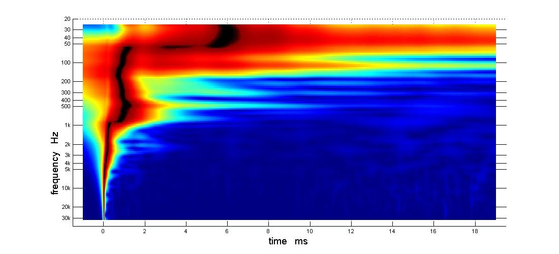
Here are wavelet spectrograms of a speaker I have up now (not very optimized at the moment). Before FIR EQ, after FIR EQ. If I'm guessing correctly, the 'DFR' would be the line made by the darkest red parts at each frequency.
Here are wavelet spectrograms of a speaker I have up now (not very optimized at the moment). Before FIR EQ, after FIR EQ. If I'm guessing correctly, the 'DFR' would be the line made by the darkest red parts at each frequency.
Attachments
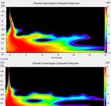
I'd second that guess.
Sure is easy to see where the room takes over.
BTW: I finally did get all 3 drivers time aligned, just this afternoon. The attached graph is w/o FIR, in fact no XO or filters at all; just three drivers with precise DSP delays of 2 ms on the mids and 2.19 ms on the CD.
Those DSP delays should be a good starting point for the XO (tomorrow).
Using the 3 measurement method, each driver separately and then both together, I just couldn't find alignment. I may not have looked for the CD to be delayed more than the mids, that is somewhat counter intuitive. The other thing that made it hard is that both bass bin and synergy are horns that have significant group delay that varies with frequency. With APL you not only can tell when you have it right but you can readily see the effect of small changes of delay.
Attachments
- Home
- Loudspeakers
- Multi-Way
- My Synergy Corner Horn and Bass Bins