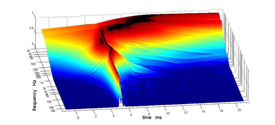
I went down to the garage with the intention to try the Harsch XO again but got distracted. I noticed the discontinuity in group delay at the woofer-Synergy XO and ended up working on that. Fortunately, I was able to go back and forth between APL and REW without any problemat thumps, screetches or howls.
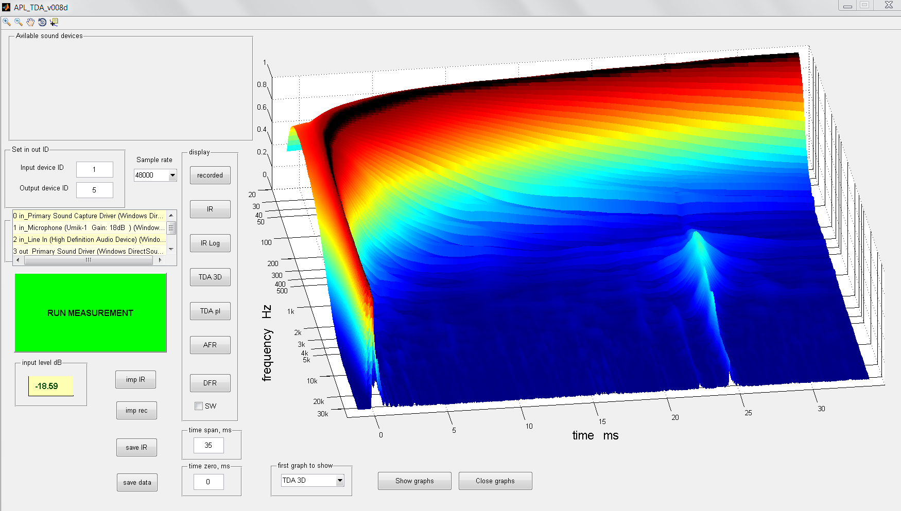
Here is what I ended up. First the APL view of my starting point:
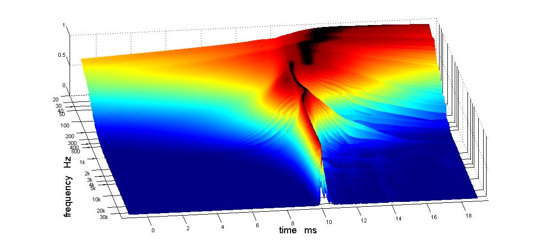
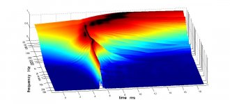
What I ended up with:
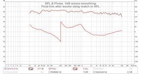
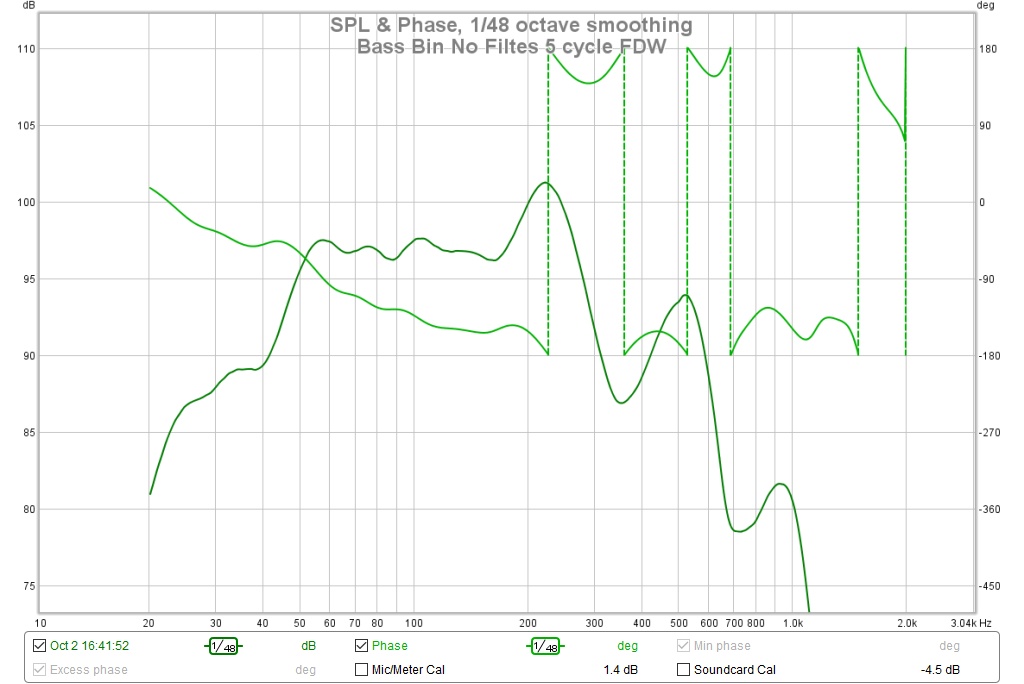
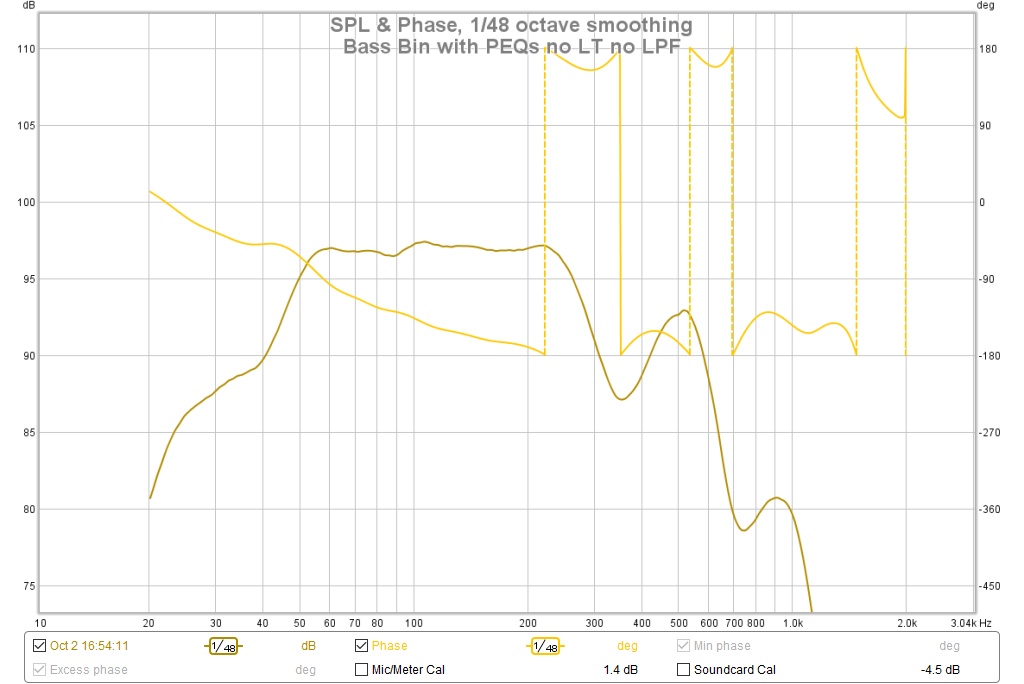
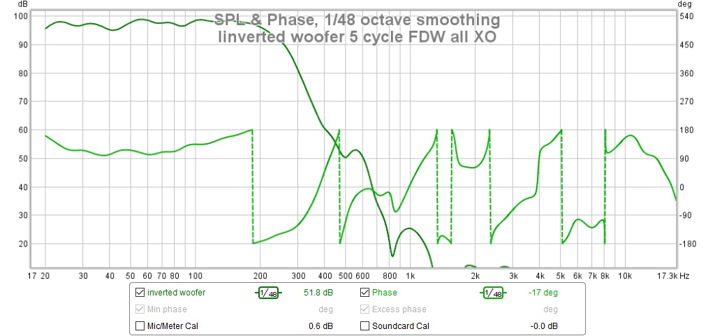
and a REW measurement 5 cycle FDW smoothing:
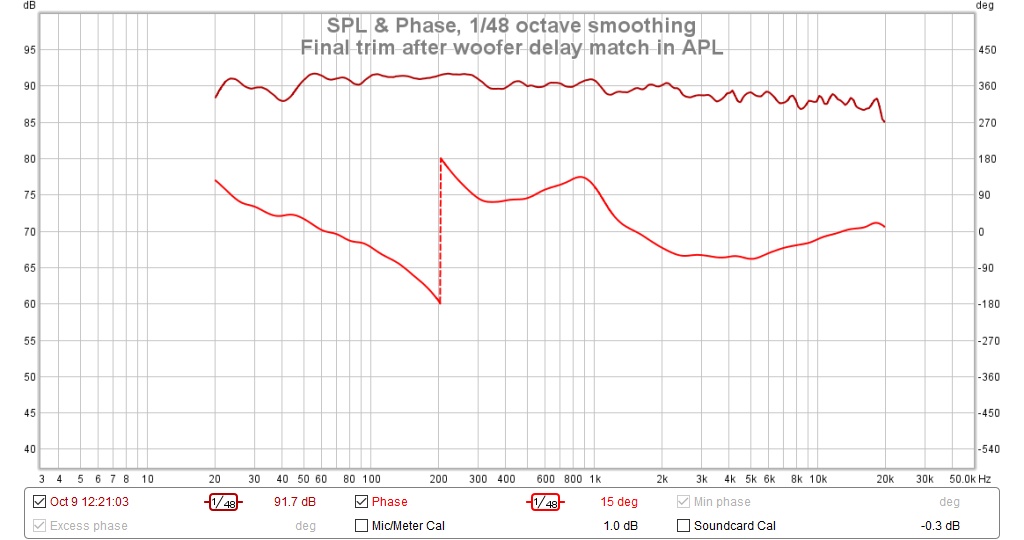
In the rew plot the phase is relatively flat with a phase flip at the 210 hz XO between woofer and Synergy. This is a 5 cycle FDW plot which smoothes both FR and phase.
In the APL plot we see group delay is straight near the 210 Hz XO and wavy near the 950 Hz XO between CD and mids. Way down low, we see the natural group delay rise of the sealed woofer. Above 100 Hz or so, we see group delay variation due to the slots loading the woofer acting like a horn. I won't do any correction below 50 Hz until I get these speakers up in the room. If I use subs with them, I'll just let them roll off naturally below 60 Hz. Now I have an LT that on paper should bring them flat to 20 Hz but doesn't quite make it that far in the garage.
Its the 950 Hz XO, that I"ve been advised to treat Harschly instead of simply correcting its group delay/phase via FIR. Its a relatively simple change entailing changing the CD HPF from LR4 to a Bessel 2 and dialing in the correct delay. My concern there is I need the sharper cutoff of LR4 to protect the BMS4550 CD from the relatively low XO point more than I need to reduce the FIR filtering requirements. We shall see.
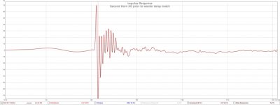
A more important question I think is what is causing the "ringing" in my latest XO IRs. Here is an IR taken prior to the woofer delay match changes:
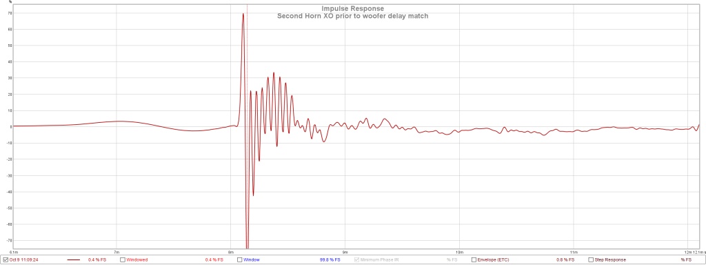
The amount of ringing is reduced in the IR with a better group delay match between the woofer and the Synergy but I must be at the limit of images for this post so I will this image later.
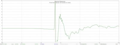
But there is none of this ringing in the earlier XOs that use a Harsch XO between the woofer and the Synergy mids:

It will be interesting to see if converting that lower XO back to Harsch will cure the ringing.
Here is what I ended up. First the APL view of my starting point:
What I ended up with:
and a REW measurement 5 cycle FDW smoothing:
In the rew plot the phase is relatively flat with a phase flip at the 210 hz XO between woofer and Synergy. This is a 5 cycle FDW plot which smoothes both FR and phase.
In the APL plot we see group delay is straight near the 210 Hz XO and wavy near the 950 Hz XO between CD and mids. Way down low, we see the natural group delay rise of the sealed woofer. Above 100 Hz or so, we see group delay variation due to the slots loading the woofer acting like a horn. I won't do any correction below 50 Hz until I get these speakers up in the room. If I use subs with them, I'll just let them roll off naturally below 60 Hz. Now I have an LT that on paper should bring them flat to 20 Hz but doesn't quite make it that far in the garage.
Its the 950 Hz XO, that I"ve been advised to treat Harschly instead of simply correcting its group delay/phase via FIR. Its a relatively simple change entailing changing the CD HPF from LR4 to a Bessel 2 and dialing in the correct delay. My concern there is I need the sharper cutoff of LR4 to protect the BMS4550 CD from the relatively low XO point more than I need to reduce the FIR filtering requirements. We shall see.
A more important question I think is what is causing the "ringing" in my latest XO IRs. Here is an IR taken prior to the woofer delay match changes:
The amount of ringing is reduced in the IR with a better group delay match between the woofer and the Synergy but I must be at the limit of images for this post so I will this image later.
But there is none of this ringing in the earlier XOs that use a Harsch XO between the woofer and the Synergy mids:
It will be interesting to see if converting that lower XO back to Harsch will cure the ringing.
Attachments
-
 tda 3d woofer delay matched to synergy.jpg56.4 KB · Views: 463
 -
 Final trim after woofer delay match in APL.jpg126.8 KB · Views: 483
 -
 tda 3d showing delay mismatch at xo to woofer.jpg54.2 KB · Views: 463
 -
 First Horn Harsch XO woofer to mids.jpg62 KB · Views: 457
 -
 Second Horn XO prior to woofer delay match.jpg66.8 KB · Views: 462
Missing image from the last post
Here is the APL view of the XO with improved group delay match between woofer and Synergy mids:

Unfortunately, I don't have APL_TDA graphs for the Harsch woofer-mid XOs.
Here is the APL view of the XO with improved group delay match between woofer and Synergy mids:
Unfortunately, I don't have APL_TDA graphs for the Harsch woofer-mid XOs.
At 210 you call it phase flip, it really isn't. It (REW) wraps the phase but it still is a continuous line. If you choose unwrap phase you'll see what I mean. REW just tries to keep it between +180 and -180 and continues at the bottom. If you already knew this I'm making a fool of myself trying to explain 😉.
At 210 you call it phase flip, it really isn't. It (REW) wraps the phase but it still is a continuous line. If you choose unwrap phase you'll see what I mean. REW just tries to keep it between +180 and -180 and continues at the bottom. If you already knew this I'm making a fool of myself trying to explain 😉.
Make that "apparent phase flip"
I still think the phase handoff isn't quite smooth. You seem to be trying to stay close to zero with the timing of the mids for no obvious reason. Are all drivers connected in positive polarity?
Do you call it "apparent phase flip" because it crosses 180 degrees there? In other words it will be lagging by half a cycle?
I can't see the win here... You shouldn't have such a hard knee at ~900 Hz in phase if the handoff was smooth. You're trying to bend it back by having the mid fire sooner than it should. The phase bends/rotates when you start to use a crossover, even in an active situation. You can't try to keep CD and mid "in time" and have smooth phase. The crossover isn't linear phase (yet). The crossover will cause the mids to be late and CD to be early due to their separate crossovers and you time them to hand off smoothly.
Do you use LR4 crossover settings on top of the band pass behaviour the entry port into the horn gives to the mids? In an active setup the LR4 name by itself means nothing. It's the acoustic shape the filter causes that's important, that should follow the LR4 shape.
In a conventional setup one could "theoretically" make the mid Frequency Response flat (for about 2 octaves past the crossover point) and then apply a text book LR4. (by selecting it from the settings in your particular device)
In this case there's a roll off already due to the band pass function of the entry point into the horn. Forget the named crossovers and look at the real acoustic slopes of the separate drivers first. Then figure out what's needed to get them into a (named) text book shape.
You can't have a true LR4 by selecting it in a program or device, not unless it was showing flat FR prior to applying that filter. So electrically you may only need a second order filter on the mids. It already rolls off due to the entry port's band pass function.
Am I way off base here by suggesting all this? Did you select LR4 crossover slopes in the active settings? Or did you look at the actual output of the separate drivers and then applied a slope to make it behave like a (text book) LR4 slope acoustically.
Last edited:
Hi Wesayso:
I've studied all that - about acoustic slopes - but never gone to the extra effort of defining a reference response and EQing to it at the individual driver level. I've had success just eyeballing it instead. And its fallen into place quite readily. Both the CD and the bandpass mids have significant rolloff just past the XO point so it hasn't been hard to get what you see in my measurements. No doubt the actual slopes are steeper than 4th order.
I didn't think the extra effort was justified inside a Synergy horn. There you get a point source and there is no concern about what happens to the power response around XO or about lobing. The goals are flatness in frequency and phase. The Harsch gets you that flat phase but gives you a bump in the frequency response. Its hard to say what is best especially when the IIR result can be shaped with FIR almost without restriction.
Your comment about the knee in phase was very helpful. For someone giving lip service to linear phase I paid surprisingly little attention to it when tuning the XO. Point taken.
I will see what I can do about that knee in the phase. It might be as simple as tweaking the relative delay between the two drivers. Initially I set that to line up what turned out to be the step responses 🙂 and then I fine tuned it to flatten the frequency response in the XO region. That helped a little ( I still have bumps in the FR at XO) but I think there is room at least to affect the phase, if not optimize it.
I will try not to speak so loosely in the future.
Jack
Sorry, I forgot to mention in my original post that in achieving the woofer-mid delay match I ended up inverting the woofer. I set the delay using APL then brought up REW and saw a null in the FR which I fixed with a phase flip, er inversion.Do you call it "apparent phase flip" because it crosses 180 degrees there? In other words it will be lagging by half a cycle?
And forgot again when I composed that quick response. A sign of advancing senility I'm afraid. You shouldn't worry about what I know or don't know because I'm as likely to have temporarily mislaid what I did know.
Well it's hard to guess what you know from this side of the keyboard, sorry for that. 🙂
I react to what I see in the graphs. For instance, with the mid/woofer hand off in the APL plots I clearly see 2 separate drivers fire at different timings. Meaning 2 black areas showing in the plot side by side. The resulting SPL level is about right but the timing isn't.
With the digital delay you have available you shouldn't have to use inverted polarity. But the steepness of the slopes will cause more phase rotation and delay.
I'll post a sample of an APL plot using second order slopes. It is a Troels Gravesen design in an excellent room. Not a synergy but it does show perfect handoff from one driver to the next. Using higher order slopes than that will result in more time delay.
Do you see how smooth the transition is? Now this is a room that would make just about any of us here jealous. But it shows if you pay attention to detail like Troels does in his design it does show up in the end result.
Source of that plot: http://www.diyaudio.com/forums/full-range/273971-group-delay-questions-analysis-50.html#post4581047
The room it is taken in: https://www.gearslutz.com/board/studio-building-acoustics/817205-my-listening-room.html
Although this is a second order crossover, all drivers fire in positive polarity by offsetting the tweeter position on the baffle.
Every bump in the FR you EQ will cause phase to alter as well, so every little detail counts.
A 4th order crossover will look different, not as smooth a transition as the plot above. But yours wiggles trough time. It would be wise to get to the point where you have to fix as little as possible with FIR. Fir correction isn't magical, it cannot fix everything. The more you can fix with other means the closer to ideal you can get.
So far your measurements show a pretty clean result in your garage, not many early reflections and all down by a significant amount. The rest is up to you 😀.
About speaking loosely, it's your thread, do as you like.... but I do think it will be hard for others to follow your thinking. I know it is for me 🙂.
Last edited:
Hi Wesayso:
I had to look twice at your posted APL graph to realize it was someone else's speaker. It looks suspiciously like a picture of my loopback signal with a ghost. That gives me something to aim for.
I can't argue that a 2nd order XO will have less delay than a 4th order but that isn't the only consideration. My problem is that while I may be aware of the issues I don't have much of a base of experience from which to make the tradeoffs. There isn't enough time in the day to do an exhaustive engineering analysis for each one, although that is what I should do. Instead, I'm making quick choices now with the idea of refining them over time as I gain experience and begin to understand better what is important.
You mentioned with DSP delay on tap I shouldn't need to invert the woofer at XO. However, I had just laboriously matched woofer delay to mid delay at XO. The alternative to the woofer inversion was 2.5 ms more or less delay. Which is worse?
My main concern with the upper end of the woofer's bandwidth is the roll off off axis due to the split horn path. (The smoothness of the phase through its crossover never entered my mind. During initial design I thought of phase as something to be corrected with FIR, if necessary) As regards that handoff between drivers, I thought that if it were to be done, best done quickly - to minimize variation across the listening window. I tried a Harsch, it seemed to work, and I liked how it sounded. It has 4th order on the woofer combined with 2nd order on the mids so I get the high slope that my gut tells me I need. But I got away from it when I saw how much group delay variation I had in the XO region. But I think I will go back to it as a way of improving the phase transition there.
The problem with the Harsch (or any textbook XO), despite it seeming to work, is that its being applied on top of group delay that is changing due to the horn characteristics of the slots loading the woofer. There is ms-level variation in it each side of the XO between 100 and 300 Hz. I think this limits how smooth I can make the phase transition and how close I could get it to follow a textbook XO curve. Ultimately, there will be some work left for FIR in this region.
This is where I wonder if the strategy of doing the best IIR XO I can and then doing further corrections with FIR is the best. Had I started down the DSP path later, I would have bought multiple MiniDSP 2x4 HDs and been able to flatten both frequency response and phase of the individual drivers as a preliminary to the XO filters and then done the XO itself with linear phase filters. This strikes me as a better way of doing things in this case, where I have that changing group delay to deal with although it would replase the balanced audio outputs of the MiniDSP 2x8 with single ended RCA.
I hope you continue to point out things I could do better; that is exactly what I need. Even if I do seem to push back, I'm still listening very closely and ultimately taking your advice in one way or another.
Jack
Attachments
Have you done measurements with the seperate drivers, including an APL plot?
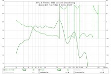
Let's see what the woofer does by itself, with and without lowpass.
Let's see what the woofer does by itself, with and without lowpass.
I have some of what you request but I won't be able to get the rest until tomorrow AM.
Here is the unfiltered driver with 5 cycle FDW:
and here it is with that peak at 220 Hz flattened:
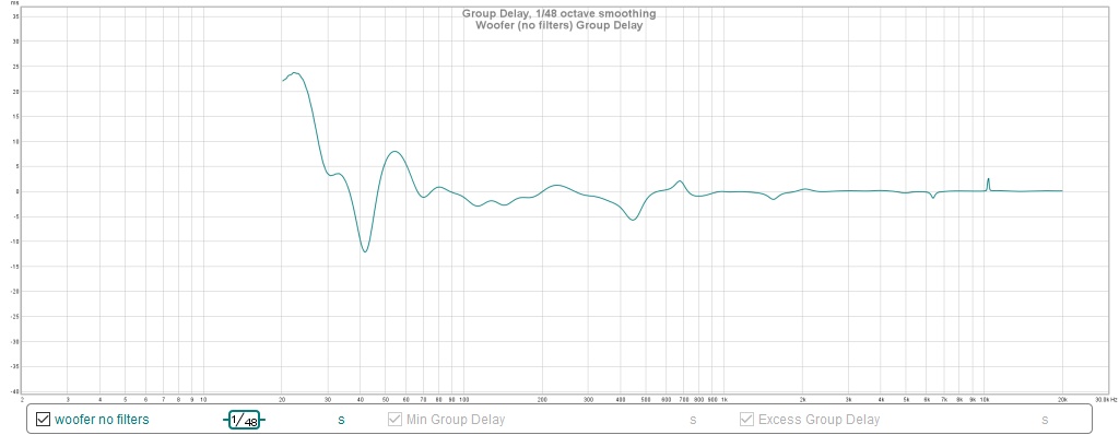
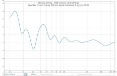
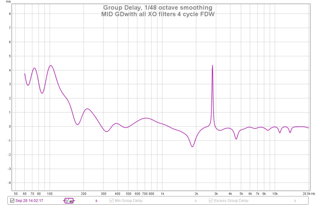
Here is the group delay of that same flattened woofer measurement.
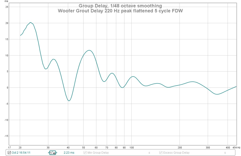
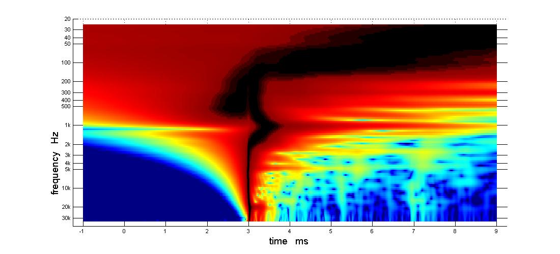
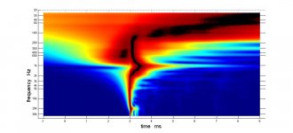
Correlate that "bump" in the GD curve at 100 Hz with my latest APL _TDA graph:

A high resolution view of that is interesting in that it masks instead of accentuates the delay discontinuities of the standard graph.
There is definitely a room effect going on at the 950 Hz XO point, which make that XO challenging with these in-garage measurements.
I don't have any woofer only APL measurements and at least for this gen XO didn't take any of the woofer alone with the final XO filters and PEQs in place. Something to do tomorrow...
Here is the unfiltered driver with 5 cycle FDW:
and here it is with that peak at 220 Hz flattened:
Here is the group delay of that same flattened woofer measurement.
Correlate that "bump" in the GD curve at 100 Hz with my latest APL _TDA graph:
A high resolution view of that is interesting in that it masks instead of accentuates the delay discontinuities of the standard graph.
There is definitely a room effect going on at the 950 Hz XO point, which make that XO challenging with these in-garage measurements.
I don't have any woofer only APL measurements and at least for this gen XO didn't take any of the woofer alone with the final XO filters and PEQs in place. Something to do tomorrow...
Attachments

Once we see each driver with crossover engaged we might know more. I still think the mid is comming in way too soon.
Too soon relative to the woofer or to the CD?
Why do you say that?
The recent changes were to add I think 1.4 ms delay to both CD and mid to bring them closer in time to the woofer, aiming for alignment at the 210 Hz XO. If you look at the standard dynamic range APL graph, you see the straight black line indicating delay match extending down past the XO almost to 100 Hz, where the black line extends upwards and to the right, reminiscent of the REW group delay curve of the woofer.
What confuses things is that "blob" to the left of the main line around 400 Hz. That is an artifact of the recent changes which were only to the woofer XO and EQ parameters. I should point out that the woofer response has a second peak there that could conceivably be being brought up by APL, but I'll concede it should be down far enough to not show up there..
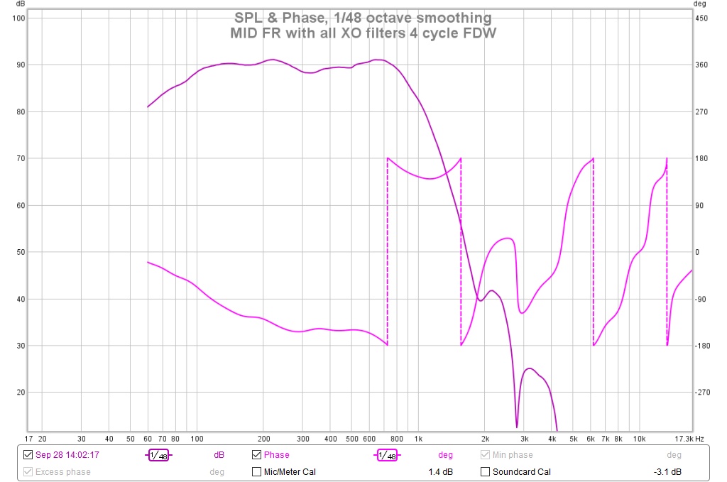
Let's look at the mid to see if it could be the culprit. It seems unlikely to me.
Why do you say that?
The recent changes were to add I think 1.4 ms delay to both CD and mid to bring them closer in time to the woofer, aiming for alignment at the 210 Hz XO. If you look at the standard dynamic range APL graph, you see the straight black line indicating delay match extending down past the XO almost to 100 Hz, where the black line extends upwards and to the right, reminiscent of the REW group delay curve of the woofer.
What confuses things is that "blob" to the left of the main line around 400 Hz. That is an artifact of the recent changes which were only to the woofer XO and EQ parameters. I should point out that the woofer response has a second peak there that could conceivably be being brought up by APL, but I'll concede it should be down far enough to not show up there..
Let's look at the mid to see if it could be the culprit. It seems unlikely to me.
Attachments
The mid is too soon relative to the CD, both of them are too soon relative to the woofer.
You're using 4th order crossover or more, that means a significant phase rotation/delay.
You're shooting for that straight line in APL but you're not going to get it by using IIR filters of the 4th order, unless they are of the linear phase kind.
Look at this APL_TDA document on page 4: http://aplaudio.com/downloads/Introduction-to-TDA.pdf
That's a 4 way 4th order network. See how the line isn't straight? I even suspect some phase correction was used here.
Move on to the next page to see an 8th order 2 way without phase correction.
You can't shoot for the straight line without altering time (with FIR filters).
I hear you but I'm still confused as to why you say that. I got to this time alignment by measuring each driver separately with all its XO filters on and then lining up the step responses with DSP delay. I might have changed the DSP settings by a few tens of microseconds but no more, so I don't see how I could be so far off. I do see that the timing is less than perfect but I wouldn't characterize those imperfections the way you did.
The time alignment is muddied by 3 things:
1. The woofer's group delay varies fairly strongly with frequency. I think at XO is where we want to set alignment
2. There is a reflection/room resonance right on top of the mid-CD XO
3. We don't know where that circa 400 Hz early response blob in APL_TDA is coming from.
Looking at the mid CD in APL, I see that the 800Hz and down region of the mid comes later than the 1200 Hz and up region of the CD. That suggests to me that the mid is firing late if at all. But looking at phase in REW, I see the knee you referred to earlier.
So there are too many things for me to work on this morning. I'll list them here for my own sake:
1. See if I can clean up the room effects around 1 Khz by strategic absorber placement
2. See if I can straighten out that knee in the mid CD XO phase by playing with dsp delay
3. Get a woofer only measurement in APL. See if that sheds any light on the early response blob circa 400 Hz that we see in APL_TDA. Put a PEQ notch on that circa 500 Hz secondary peak in the woofer output to see if that clears it up.
4. Get a woofer only measurement in REW with all XO filters in place
5. Convert the woofer-mid XO to harsh
6. Convert the mid-CD XO to harsh
Last edited:
this is coming to you in real time from the lab
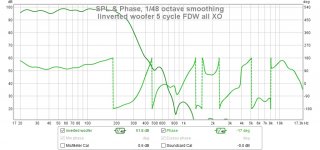
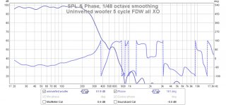
The only difference between these two measurements is pressing the "INVERT" button on the woofer output of the miniDSP

That isn't how I expected the phase response to change with a simple supposedly frequency independent inversion
The only difference between these two measurements is pressing the "INVERT" button on the woofer output of the miniDSP
That isn't how I expected the phase response to change with a simple supposedly frequency independent inversion
Attachments
Woofer only in APL_TDA
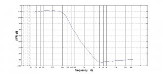
First the AFR
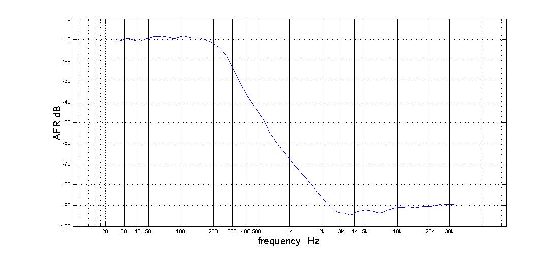
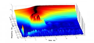
Almost couldn't ask for better than that. Here is the 3D display
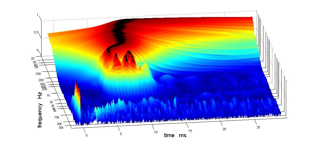
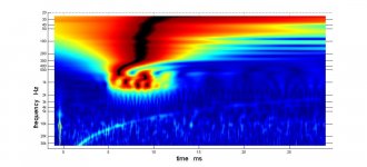
and the 2D display, both with a 10 ms time offset

From the AFR and the REW, we know those artifacts on the APL graphs are fairly far down the attenuation slope. The way APL brings them up can be confusing.
From looking at the 2D picture and the REW GDs posted earlier, I would say that the delay on the woofer low pass filter slope is due to the low pass filter. If I used only a 2nd order filter, the woofer pass band would be delayed less, but its a fairly constant delay through the upper half of the passband so I don't think the filter order is hurting me. It should get mostly compensated when I set DSP delays into the CD and mid to line them up with the woofer. The group delay in the lower half of the passband isn't due to the low pass filter.
(not being defensive here, just trying to be analytical, feel free to shoot holes in my arguments; that is how I learn)
First the AFR
Almost couldn't ask for better than that. Here is the 3D display
and the 2D display, both with a 10 ms time offset
From the AFR and the REW, we know those artifacts on the APL graphs are fairly far down the attenuation slope. The way APL brings them up can be confusing.
From looking at the 2D picture and the REW GDs posted earlier, I would say that the delay on the woofer low pass filter slope is due to the low pass filter. If I used only a 2nd order filter, the woofer pass band would be delayed less, but its a fairly constant delay through the upper half of the passband so I don't think the filter order is hurting me. It should get mostly compensated when I set DSP delays into the CD and mid to line them up with the woofer. The group delay in the lower half of the passband isn't due to the low pass filter.
(not being defensive here, just trying to be analytical, feel free to shoot holes in my arguments; that is how I learn)
Attachments
Wesayso:
Just took some new plots that tell me that mid/CD are indeed firing (way) too soon but these look different than previous days; not sure why yet. looks like I changed my DSP delays away from alignment at some point along the way, fixed one problem, caused another; didn't regress; shame on me.
that is why I liked ASIC design - regression was automated
stay tuned
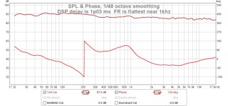
result of DSP delay tweaks on mid-CD XO
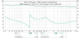
Yes, by playing with dsp delay, I can indeed reduce the so called phase knee near the XO point. Unfortunately this comes at the cost of frequency response.
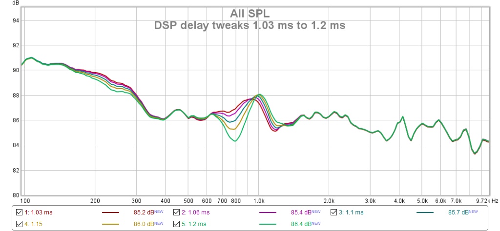
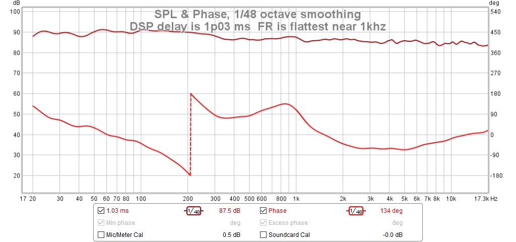
The flattest frequency response was with the original delay
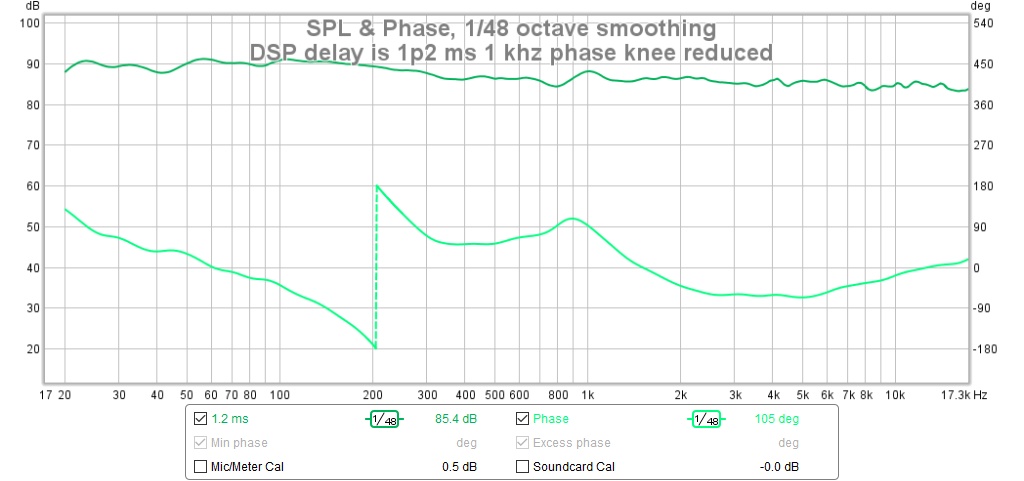
Increasing delay did indeed reduce the phase knee
Yes, by playing with dsp delay, I can indeed reduce the so called phase knee near the XO point. Unfortunately this comes at the cost of frequency response.
The flattest frequency response was with the original delay
Increasing delay did indeed reduce the phase knee
Attachments
- Home
- Loudspeakers
- Multi-Way
- My Synergy Corner Horn and Bass Bins