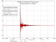
Due to the scale (your signal starts at 15 ms) we only see 5 ms worth of the IR.
I expect to see something at 11 ms (after the initial peak, so at ~26 ms, a big reflection) But also something earlier
The Filtered IR should also show some peaks with high SPL. After the initial peak I mean.
Look into the area after the initial peak, there should be some clear peaks, at least one at ~11 ms.
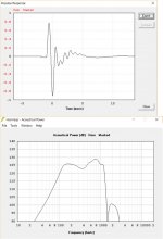
Should look something like this (only with bigger peaks following the initial signal)

My quest was to get them all down by at least -20 dB after the initial peak. That still doesn't tell you much
about lower frequencies though, even this graph is a combined representation of all frequencies. But it usually
shows the bigger reflections (so you know at what time they arrive and how loud they are, sort of anyway)
I expect to see something at 11 ms (after the initial peak, so at ~26 ms, a big reflection) But also something earlier
The Filtered IR should also show some peaks with high SPL. After the initial peak I mean.
Look into the area after the initial peak, there should be some clear peaks, at least one at ~11 ms.
Should look something like this (only with bigger peaks following the initial signal)
My quest was to get them all down by at least -20 dB after the initial peak. That still doesn't tell you much
about lower frequencies though, even this graph is a combined representation of all frequencies. But it usually
shows the bigger reflections (so you know at what time they arrive and how loud they are, sort of anyway)
Last edited:
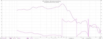
The delta path length for the floor bounce is .8 to .9 ms across the couch. 2.65 ms for ceiling bounce.
The floor bounce really widens the mid bass trace. I'm hoping that a carpet and pad upgrade will clean up the upper midbass part of this and building the 2nd set of bass bins will take care of the first octave and half below woofer XO. Perhaps I could push the woofer XO up even higher and then make it steeper.
The floor bounce really widens the mid bass trace. I'm hoping that a carpet and pad upgrade will clean up the upper midbass part of this and building the 2nd set of bass bins will take care of the first octave and half below woofer XO. Perhaps I could push the woofer XO up even higher and then make it steeper.
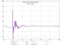
That's better (to read). How does the IR look at 1 m on the same scale (the cleaner APL plot shows way less reflections). Just for reference...
We've got to figure out where the reflections are coming from, but also how many of those wavy lines between 0 and 4 ms are reflections. A cleaner IR (without reflections) should teach us that.
I've got to go though (sadly). Way past midnight here...
We've got to figure out where the reflections are coming from, but also how many of those wavy lines between 0 and 4 ms are reflections. A cleaner IR (without reflections) should teach us that.
I've got to go though (sadly). Way past midnight here...

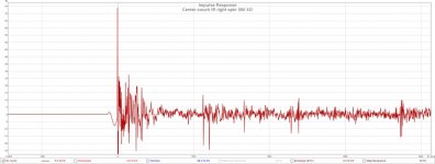
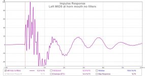
Set it to "dB FS" instead of "%FS", zoom in on the first ~100 or 50 ms.
To switch to SPL instead of %FS, just hoover the graph and it should be at the top left.
That should give you the initial peak reaching 0 dB, followed by the reflections.
No filters (yet)...
Don't forget, everything close to the microphone can give you reflections too! If you have a leather couch,
drop a folded blanket over it... look for stuff closely behind the microphone. (not being there at 1 m)
Last edited:
We've got to figure out where the reflections are coming from, but also how many of those wavy lines between 0 and 4 ms are reflections.
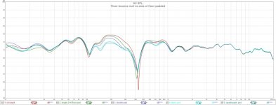
I've been around the room padding various surfaces. The most telling though is what happens when I pad more and more of the floor area between the speaker and mic. I've got two 4" thick fiberglass panels and 2 2.5'x6.5' foam futon mattresses that I spread out on the floor and measured successively
The more area I cover, the less deep the notch at 430 Hz and the lower the bump between 100 and 300 Hz. Clearly, I'm not getting as much vertical directivity as I hoped in that band, maybe I can get more by playing with the XO or perhaps it will have to wait for the 2nd pair of bass bins. Its clear however that the issue is floor reflection in this range.
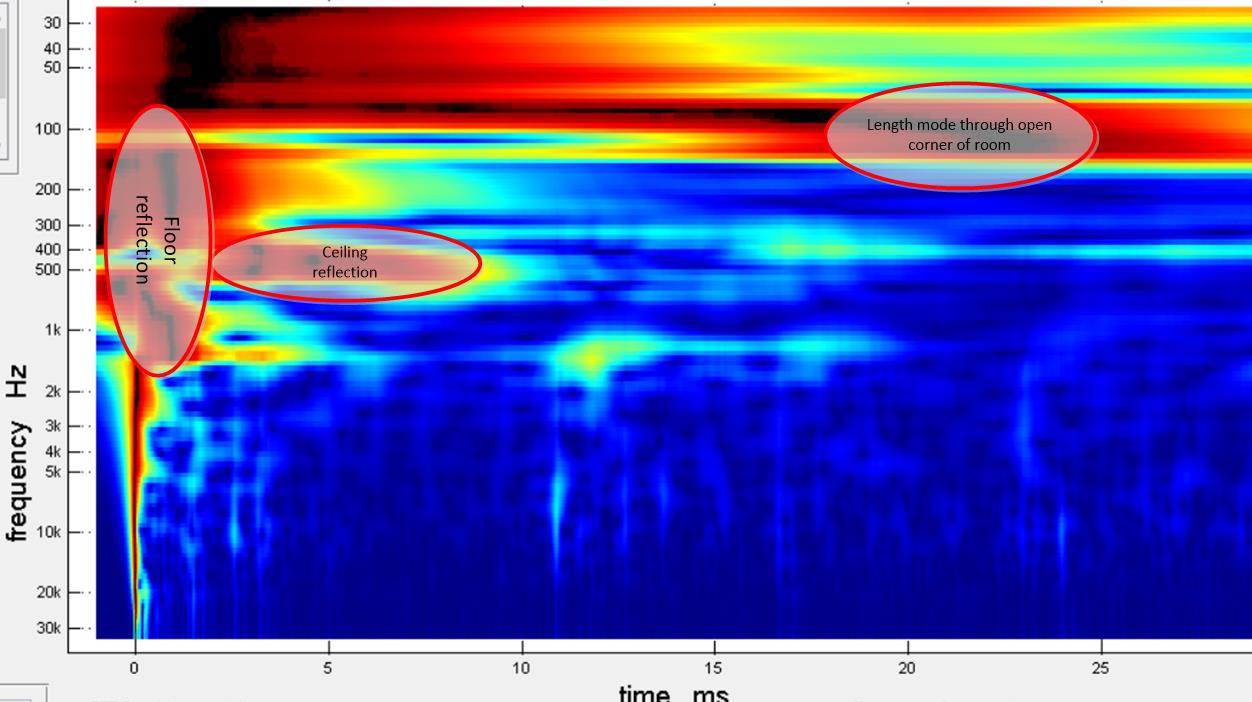
Here is the TDA graph with all the floor pads in place
Given that the floor pads are in place, the reflections delayed 2.6 ms - 5 ms are from the ceiling. I have confirmed this to some extent with an absorber pad balanced on top of a step ladder, but not while the floor was padded.
Its like peeling an onion, you have to get rid of one layer of reflections to get visibility into the next.
Wesayso: you and RA7 sidestepped these pesky floor and ceiling reflections with your tall line arrays. Walls are much easier to treat than floor and ceiling.
Attachments
I'd try to bring the speaker into the room, say 50 cm from the side and back wall and measure at the listening position. Just to see what it does, even if you have softened the floor reflections, there still seem to be many early reflections going on. I'd say they are earlier than I'd expect a ceiling reflection to come into play. If that clears up the first 4-5 ms, we would learn something from this exercise.
I could be wrong though, yet, it may be worth a shot just to try.
Yes, I agree the arrays we use have advantages as far as floor and ceiling reflections are concerned. I only treated one side wall and 2 other places at/near the listening position to counter all the big reflections I had.
I did have visions of a synergy in the middle of a bass array. But the problem areas we see in your APL plot come too early and higher in frequency than I expected. It looks like you have a very restless mid area from 200 Hz to 1 KHz.
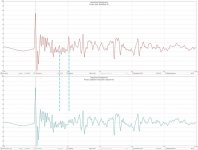
Compare the IRs with and without floor pads below. I've put dashed blue lines to highlight spikes taken out by the floor pads. The calculated path length distance for floor reflection is .91 ms (just remeasured) and 3.09 for the ceiling bounce. The 2nd dashed blue line is right where you would expect a floor reflection to come from. The spike lined up with the first dashed blue line is early, but the spike was eliminated by the floor pads.

This floor padding experiment shows that floor reflections come from the entire floor area, not a single spot; must be some scattering going on.
Earlier (in the garage) I did experiments padding the side walls next to the horn that convinced me the near side walls were not sources of these close in reflections. I'm afraid pulling the horn out of the corner would just add more reflections to the mix; confusion not enlightenment. plus hurt my back.
This (diffraction from horn mouth) might be the cause of some of the early ringing in the IR. The horn is 40 cm long so anything earlier than that is inside the horn - mouth reflections, mid energy reflected from the apex, HF reflected from mid holes, diffraction from the un-terminated horn mouth...
Attachments
Last edited:
I did have visions of a synergy in the middle of a bass array. But the problem areas we see in your APL plot come too early and higher in frequency than I expected. It looks like you have a very restless mid area from 200 Hz to 1 KHz.
Yes, that was my vision also, but its not fully implemented. I expected the vertically arrayed woofers would give vertical directivity from woofer XO down an octave and a half or so. I also expected more absorption from my carpet. The carpet I have now does very little; its what the builder put in the house without upgrade. New thick wool carpet on a felt pad should take care of 500 Hz up to where the Synergy has pattern control. The carpet will help between 350 and 500 but its less effective at LF. I almost got out to a carpet store today.
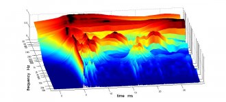
Here is where I think the major reflections are coming from
This was taken with the floor pads in place so it doesn't show the worst of the floor reflections but masking them allows us to see the ceiling reflections in the 400-500 hz range.
Notice how the floor reflection fuzz goes away around 1300 Hz where the horn gains vertical pattern control.
This was taken with the floor pads in place so it doesn't show the worst of the floor reflections but masking them allows us to see the ceiling reflections in the 400-500 hz range.
Notice how the floor reflection fuzz goes away around 1300 Hz where the horn gains vertical pattern control.
Attachments
I guess Bill was spot on in the 3th post of this thread...
No free lunch with the shorter dimension at the vertical path of the horn.
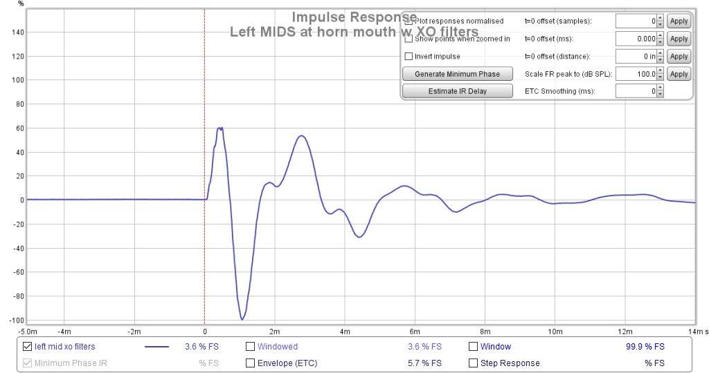
I do have another question for you. Does the negative spike, following the initial pulse of the IR go all the way down to 100%?
To me this still seems like the mids in the horn are connected in negative polarity, following the positive tweeter pulse. We've talked about it earlier, I'm just trying to "read" the IR. The phase plot of the 1m measurement wasn't that clear to see, except the tweeter starts at 0, dips down to almost -90 degree and then jumps back up to more than +90 (a 180 degree difference).
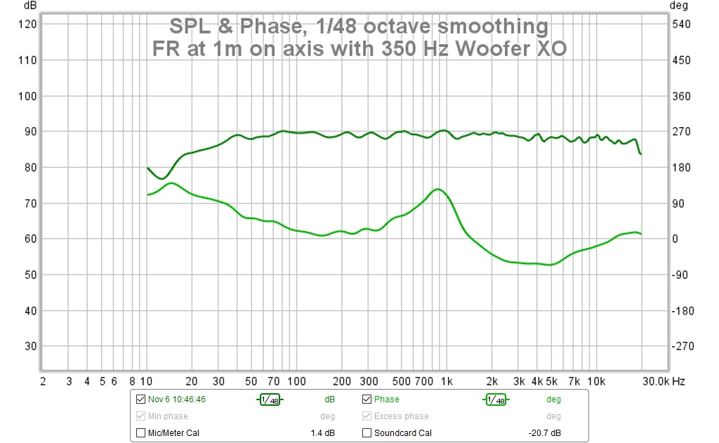
Totally separate from the floor ceiling discussion I still believe we should be able to do better here. With the short wave lengths (in ms) it hardly shows up in the APL graph, but the mid - tweeter handoff still seems a bit weird to me.
Looks like a neat concept. I think you'll still get boundary nulls from ceiling and floor, though. The lower vertical pattern control frequency for the rectangular horn will be much higher than for horizontal propagation, so there will be reflections off the floor (causing a null at I'm guessing around 150-230Hz) and one from the ceiling also. I have that issue on my Synergy clones, too. Allison effect is a bitch.
It wouldn't be as nice cosmetically, but have you considered making a square rather than rectangular horn so the vertical is controlled better? The vertical angle would be wider but would extend down to more useful frequencies. To make a narrower angle to a given frequency, the horn has to be (against intuition) larger in dimension, so the narrower angle causing a smaller dimension hurts quickly.
No free lunch with the shorter dimension at the vertical path of the horn.
I do have another question for you. Does the negative spike, following the initial pulse of the IR go all the way down to 100%?
To me this still seems like the mids in the horn are connected in negative polarity, following the positive tweeter pulse. We've talked about it earlier, I'm just trying to "read" the IR. The phase plot of the 1m measurement wasn't that clear to see, except the tweeter starts at 0, dips down to almost -90 degree and then jumps back up to more than +90 (a 180 degree difference).
Totally separate from the floor ceiling discussion I still believe we should be able to do better here. With the short wave lengths (in ms) it hardly shows up in the APL graph, but the mid - tweeter handoff still seems a bit weird to me.
Last edited:
Bill wasn't telling me anything I didn't know; I just thought it would be easier than it has been to absorb the floor and ceiling reflections.
Making the horn taller doesn't really help. It lowers the pattern control frequency but at the same time it widens the pattern so you still get floor reflections in your face. A 90x90 horn is too wide and I wanted side walls parallel to corner walls. I also wanted to minimize the depth of the horn. And I didn't want the horn firing sound up from near floor level so I ended up where I am. Wasn't looking for a free lunch. I was willing to absorb what my flare didn't control; now I have to pony up for the absorbers.
Yes, the negative phase spike goes to -100%. That is my original woofer mid XO. I was just looking at old measurements and I see the phase changes there haven't changed. If I keep looking I should be able to find some measurements that shed light on the issue of mid/cd polarity but I can't look right now - I have to go to dinner.
.
Something wrong with the mids
The mid frequency response looked so much like the simulation that I never looked at their impulse response. When I finally looked, I saw something wrong but I can't imagine what it is.
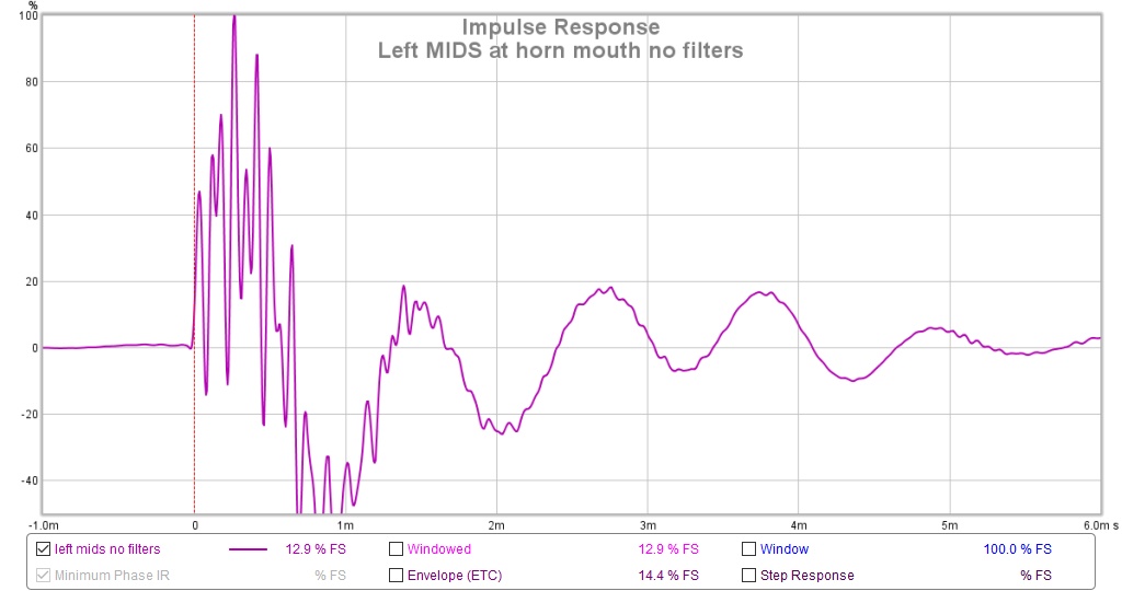
I remeasured these this morning with the mic at the horn mouth to keep the room out. I get the same picture dee[ inside at the mid ports, just higher amplitude.
I have two 4fe35 mids on each side wired in series-parallel using color coded wire which should preclude the possibility of getting some of them out of phase. The drivers themselves have different shape terminals for + and -, in addition to a red dot on the plus side. The long shallow chambers, just 1/2" deeper than the drivers are stuffed with polyester. They are sized to have no standing waves in the passband, except for the long dimension where there is enough absorption to absorb such a wave.
Fortunately, the covers are removable so I can check without too much trouble. Any ideas as to what to look for other than wiring errors?
The mid frequency response looked so much like the simulation that I never looked at their impulse response. When I finally looked, I saw something wrong but I can't imagine what it is.
I remeasured these this morning with the mic at the horn mouth to keep the room out. I get the same picture dee[ inside at the mid ports, just higher amplitude.
I have two 4fe35 mids on each side wired in series-parallel using color coded wire which should preclude the possibility of getting some of them out of phase. The drivers themselves have different shape terminals for + and -, in addition to a red dot on the plus side. The long shallow chambers, just 1/2" deeper than the drivers are stuffed with polyester. They are sized to have no standing waves in the passband, except for the long dimension where there is enough absorption to absorb such a wave.
Fortunately, the covers are removable so I can check without too much trouble. Any ideas as to what to look for other than wiring errors?
Attachments
What kind of XO filter are you using? Theory (Hornresp) follows practice (REW measurement) pretty closely. Or the other way around 😉.
But I wouldn't want to slap on a named XO to get the desired crossover result. I'd want a filter that puts the real acoustic measurement into shape. That will change the IR and phase so we can have a better hand-off to the tweeter.
Don't be too misled by the IR without any filter at all. It probably shows some extra ringing at higher frequencies that (hopefully) gets filtered out with a desired crossover slope.
Last edited:
- Home
- Loudspeakers
- Multi-Way
- My Synergy Corner Horn and Bass Bins