MIDs and CD delay increased by 3 ms
These figures speak for themselves.
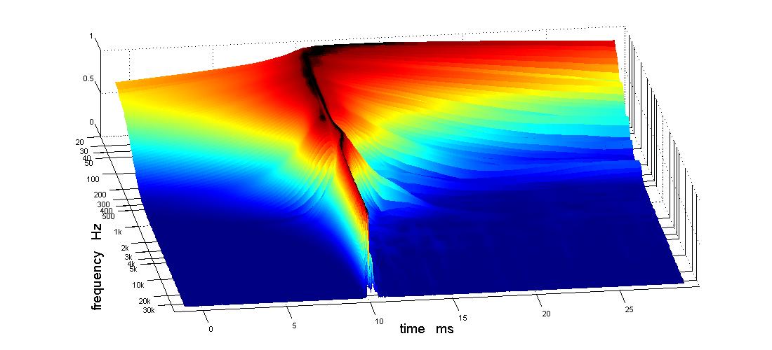
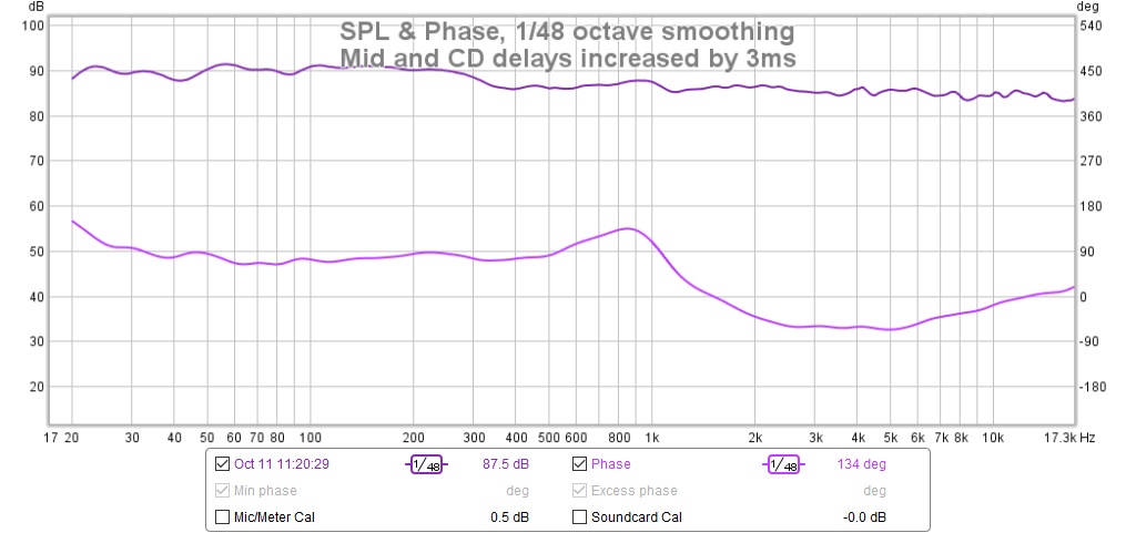
Just to be clear: these are 4th order IIR XOs
Thanks Wesayso for persistently pointing out the issues.
Jack
These figures speak for themselves.
Just to be clear: these are 4th order IIR XOs
Thanks Wesayso for persistently pointing out the issues.
Jack
Attachments
In a synergy can you not adjust the location of the ports along the axis to account for the phase rotation imposed by the crossover? I thought that is what Danley was doing to get a flat phase (other than probably some crossover delay networks). Bill mentioned that you want to keep the 1/4 wavelength reflection outside the passband, so maybe that imposes some limits.
Edit: Jack and I posted at the same time. I think you can that good for a while, Jack 🙂
Edit: Jack and I posted at the same time. I think you can that good for a while, Jack 🙂
Nc535, if your software lets you change phase display to an UNwrapped format, the phase delays and result of inversions would probably make better intuitive sense.
That said, you're close, let dsp clean up.
That said, you're close, let dsp clean up.
In a synergy can you not adjust the location of the ports along the axis to account for the phase rotation imposed by the crossover? I thought that is what Danley was doing to get a flat phase (other than probably some crossover delay networks). Bill mentioned that you want to keep the 1/4 wavelength reflection outside the passband, so maybe that imposes some limits.
Edit: Jack and I posted at the same time. I think you can that good for a while, Jack 🙂
Yeah you can move the holes but for a DIYer, that is a lot of work and not something I would entertain at this point. But this is my third generation prototype. I did some filling and re-drilling at the first stage, mostly for hole size, not location.
If I didn't have DSP to dial in relative delay between mid and CD, I'd have to use passive all pass filters. Danley said something about having written custom crossover development program to be able to do passive synergy crossovers with flat phase in a reasonable amount of time.
Last edited:
Aren't you glad you decided to invest some extra time into it? This is real progress I see here. I wonder if you could try to ease up on the low-pass slope of the midrange (and only that low-pass, don't change the CD crossover), with one step less steepness, if it's 4th order now, change it to 3th... something like that. You might need to re-adjust timing etc, but I am curious what would happen.
Or just get DSP involved like Bill said 😀.
Can you show the IR belonging to the latest plots?
Or just get DSP involved like Bill said 😀.
Can you show the IR belonging to the latest plots?
Nc535, if your software lets you change phase display to an UNwrapped format, the phase delays and result of inversions would probably make better intuitive sense.
That said, you're close, let dsp clean up.
That is a good suggestion. That inversion really fooled me; I should have dialed in more delay instead.
Raimonds said go ahead with FIR a couple of nights ago but the challenge is to see what one can do without it.
Aren't you glad you decided to invest some extra time into it? This is real progress I see here. I wonder if you could try to ease up on the low-pass slope of the midrange (and only that low-pass, don't change the CD crossover), with one step less steepness, if it's 4th order now, change it to 3th... something like that. You might need to re-adjust timing etc, but I am curious what would happen.
Or just get DSP involved like Bill said 😀.
Can you show the IR belonging to the latest plots?
I'm not done yet but for now i just want to listen to it.
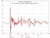
Here is the IR:
still concerned about that ringing in the IR after the initial positive and then negative peaks
Attachments

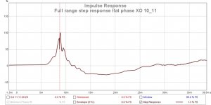
It's in compliance with the FR and phase you showed earlier. It kind of resembles what the Harsch crossovers show.
If you look at the phase curve, the top end of the CD is a bit late compared to the 2 KHz - 5 KHz part. The IR shows this too. You won't see it in the APL plot (in that same 2-5 KHz area) as it's fractions in time we're talking about.
It's much better than the previous STEP you showed though. Further fixable with FIR processing if you wish. If we can get that knee down a bit further...
If you think the CD can handle it, what I suggested for the mid could also be tried on the high-pass of the CD, again, not both, just one of the two, either mid or CD.
There is lots of headroom. Distortion products are down 50 db in that region. I'm still listening, though. Bob Dylan at the moment. This speaker makes even him sound good!
Uh-oh. Something clearly broken then. (joke)I'm still listening, though. Bob Dylan at the moment. This speaker makes even him sound good!
That's actually why XSim was developed, too. Getting linear phase required some unconventional configurations that other passive design software like PCD didn't support. In retrospect, though XSim was a nice side-benefit, I'm still convinced that passive linear-phase design isn't a great approach. FIR DSP is so simple and effective. Even on the speakers that I got to pretty-much linear phase, I still ended up using FIR to tweak things even better, so why not just save the trouble (and large number of crossover components!) let it do it all? With a coaxial synergy configuration, you have much freedom to ignore how interactions affect polar response (assuming you have on-axis response decent), so I say just get the response shape and power handling right and then let modern engineering do what it was designed for.Danley said something about having written custom crossover development program to be able to do passive synergy crossovers with flat phase in a reasonable amount of time.
(Of course, for those who shun anything digital, that approach isn't an option)
I agree. I invested in multi-channel amps and DSP from the start and although I have already accumulated a fair number of drivers I might never use in the few years I've been doing this, I don't have any left over or not quite right value Ls and Cs.
Response in roomn
Getting the speakers moved upstairs was the easy part. Taking down the equipment rack in the garage and rebuilding and re-cabling it upstairs provided multiple opportunities to screw up and I took full advantage of them. Within a few days I had all that straightened out and could listen in stereo for the first time, which I have been enjoying.
The last few days I've been tailoring the speakers to the room.
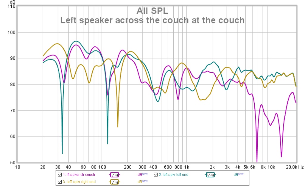
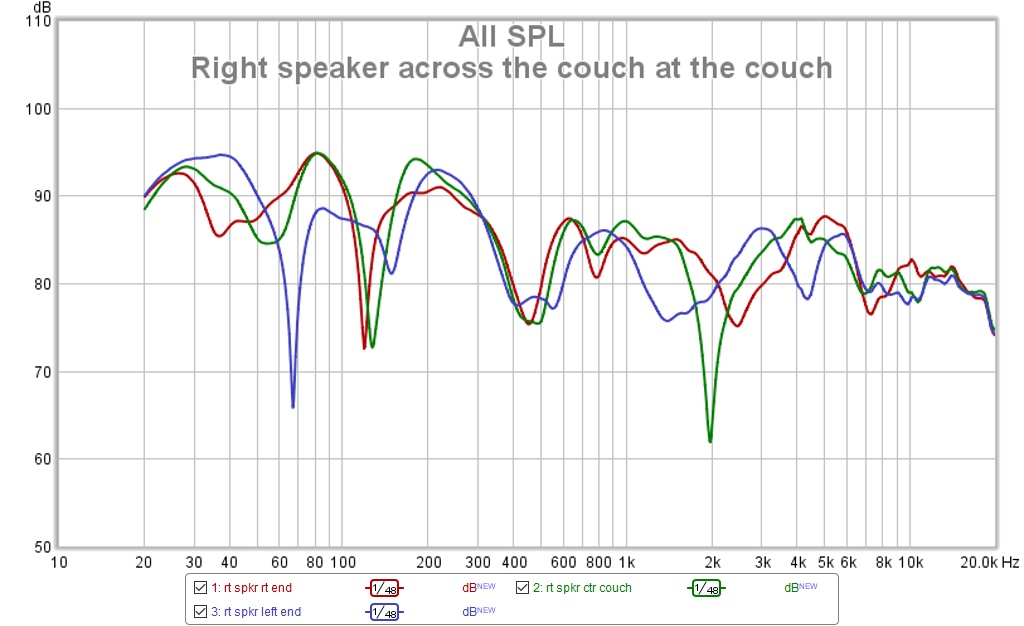
First I found they measure essentially the same in room at 1m as they did in the garage. The figure below are essentially eyeballed H polars but across the listening couch rather than at specific angles.
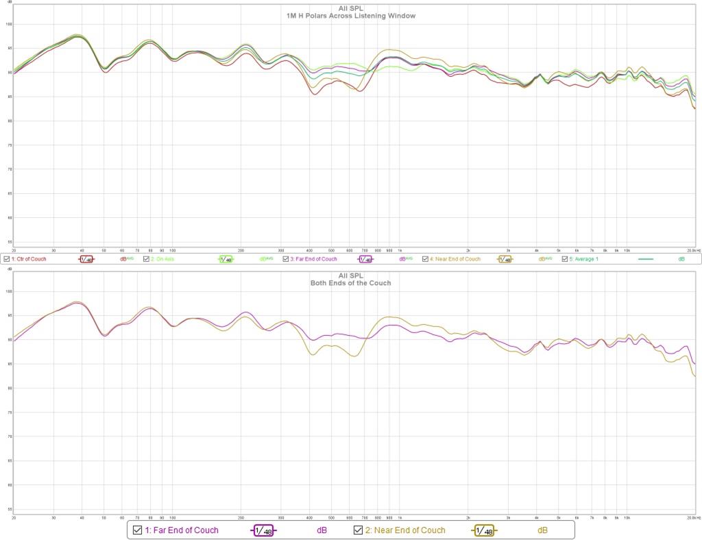
The bottom graph shows the two primary listening positions at the reclining ends of the 3 seat couch. You can see midband narrowing between 350 and 750 Hz or so but equalizing for just those end positions the effect is small.
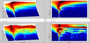
The APL_TDA graph is always instructive. Here is one taken at 1m:
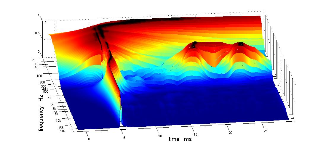
I chased that reflection around for a while but never came up with a single location that could be padded to eliminate it. That is a 100 Hz room mode that also plagues other measurements.
The room intrudes to a much greater extent out at the actual listening position.

All those reflections, from every surface except the sidewalls apparently, show up in the frequency response, even with 4 cycle FDW smoothing:
The challenge was and is how to tame the room and improve the response.
Getting the speakers moved upstairs was the easy part. Taking down the equipment rack in the garage and rebuilding and re-cabling it upstairs provided multiple opportunities to screw up and I took full advantage of them. Within a few days I had all that straightened out and could listen in stereo for the first time, which I have been enjoying.
The last few days I've been tailoring the speakers to the room.
First I found they measure essentially the same in room at 1m as they did in the garage. The figure below are essentially eyeballed H polars but across the listening couch rather than at specific angles.
The bottom graph shows the two primary listening positions at the reclining ends of the 3 seat couch. You can see midband narrowing between 350 and 750 Hz or so but equalizing for just those end positions the effect is small.
The APL_TDA graph is always instructive. Here is one taken at 1m:
I chased that reflection around for a while but never came up with a single location that could be padded to eliminate it. That is a 100 Hz room mode that also plagues other measurements.
The room intrudes to a much greater extent out at the actual listening position.
All those reflections, from every surface except the sidewalls apparently, show up in the frequency response, even with 4 cycle FDW smoothing:
The challenge was and is how to tame the room and improve the response.
Attachments
-
 fig 4 Left speaker across the couch at the couch.jpg140.8 KB · Views: 394
 -
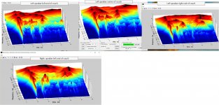 fig 3 composite tda 3d left speaker across couch.jpg206 KB · Views: 395
 -
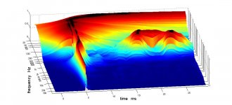 fig 2 baseline 1m fluffy floor pad.jpg61.1 KB · Views: 394
 -
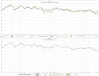 fig 1 1M H polars and couch ends composite.jpg75.8 KB · Views: 400
 -
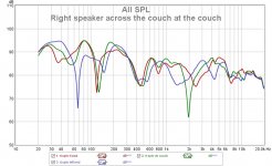 fig 5 Right speaker across the couch at the couch.jpg130 KB · Views: 390
That is the challenge alright.
I bet it makes you wonder how I got my results at the listening spot 🙂.
That APL graph I posted earlier was at the listening spot. It took me 3 (pretty big) damping panels plus FIR filter DSP to get it though.
Look at the IR and filtered IR (for SPL numbers) to get an idea where to start.
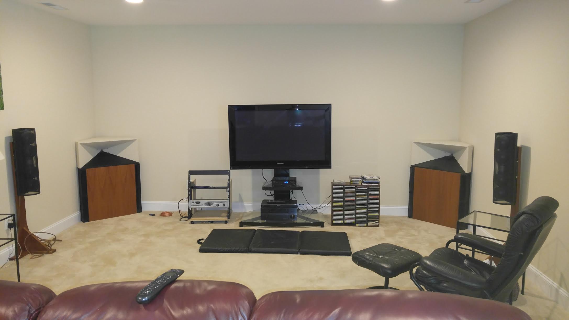
How did you aim the horns? Where are they placed?
Like this I guess... duhh... I'd like to see an IR (first 20 ms or so...)
I bet it makes you wonder how I got my results at the listening spot 🙂.
That APL graph I posted earlier was at the listening spot. It took me 3 (pretty big) damping panels plus FIR filter DSP to get it though.
Look at the IR and filtered IR (for SPL numbers) to get an idea where to start.
How did you aim the horns? Where are they placed?
Like this I guess... duhh... I'd like to see an IR (first 20 ms or so...)
Last edited:
Re-examining the slot loaded corner woofer
All positions have a floor reflection null at/around 450 Hz and various other dips and nulls. Much of this could be ameliorated, if not corrected, with more vertical directivity. That would require a higher woofer-mid crossover for a start and ultimately the second pair of bass bins stacked on top of the Synergy horn as in my original plan.
I took another look at the woofer, this time with a ground plane measurement in room and found that except for pattern narrowing due to the split sound path it was good to past 500 Hz. For this measurement, I rotated the inside end of the woofer cabinet away from the wall until the speaker axis pointed at the center of the listening couch the added a wing to the woofer cabinet, like I had in the garage. The measurements below were made with the mic at 2m distance at angles corresponding to the two end seats. With the axis aimed at the center of the couch, response on either end over the entire range should be the same by symmetry. While the woofer response falls off off axis due to the split horn path, its pattern is clearly wide enough to cover both ends of the couch.
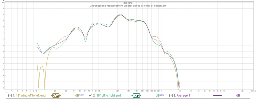
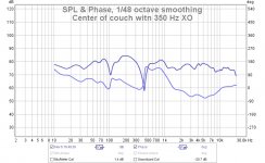
Given this BW in the woofer, I changed the woofer -Synergy XO to 2nd order at 350 Hz. The new XO measures thusly at 1m
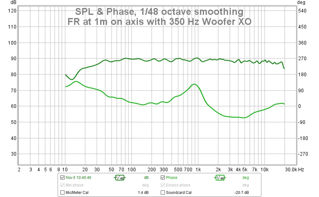
and as shown below out at the center of the couch:

I still have a prominent floor bounce null out at 430 Hz but the overall picture is vastly improved! I lost the downward tilt on the frequency response and need to restore it.
All positions have a floor reflection null at/around 450 Hz and various other dips and nulls. Much of this could be ameliorated, if not corrected, with more vertical directivity. That would require a higher woofer-mid crossover for a start and ultimately the second pair of bass bins stacked on top of the Synergy horn as in my original plan.
I took another look at the woofer, this time with a ground plane measurement in room and found that except for pattern narrowing due to the split sound path it was good to past 500 Hz. For this measurement, I rotated the inside end of the woofer cabinet away from the wall until the speaker axis pointed at the center of the listening couch the added a wing to the woofer cabinet, like I had in the garage. The measurements below were made with the mic at 2m distance at angles corresponding to the two end seats. With the axis aimed at the center of the couch, response on either end over the entire range should be the same by symmetry. While the woofer response falls off off axis due to the split horn path, its pattern is clearly wide enough to cover both ends of the couch.
Given this BW in the woofer, I changed the woofer -Synergy XO to 2nd order at 350 Hz. The new XO measures thusly at 1m
and as shown below out at the center of the couch:
I still have a prominent floor bounce null out at 430 Hz but the overall picture is vastly improved! I lost the downward tilt on the frequency response and need to restore it.
Attachments
That is the challenge alright.
I bet it makes you wonder how I got my results at the listening spot 🙂.
That APL graph I posted earlier was at the listening spot. It took me 3 (pretty big) damping panels plus FIR filter DSP to get it though.
Look at the IR and filtered IR (for SPL numbers) to get an idea where to start.
How did you aim the horns? Where are they placed?
That is quite an accomplishment if it was anything like what I faced at the start.
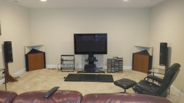
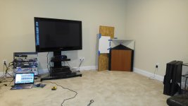
Actually it makes me wonder if I don't want to just declare victory prematurely and just enjoy the speakers. I do have a plan though. And here is how the horns are aimed. Each horn is rotated about 10 degrees away from the front wall to aim at the center of the couch. I'm going to add a big roundover to that extension wing, paint it wall color, and blend the synergy horn wall into it. The TV has to come up off the stand and onto the wall so it can be in the shadow of the wing.
Attachments
I would try and cross slightly in front of the central listening seat, making it a wider sweet spot for the seats around you. Geddes has talked about this at length and so have a few others.
Nothing wrong though with just enjoying what you got. I bet it still sounds great even if that picture doesn't look that good.
The thing I did is hunt down the biggest early (arriving within 20 ms) reflections and absorb them. If I look at your APL plot, there's something at 11 ms that reflects high frequencies but there are earlier reflections that upset the midrange.
An IR will show you how close they actually are.
- Home
- Loudspeakers
- Multi-Way
- My Synergy Corner Horn and Bass Bins