Transformation
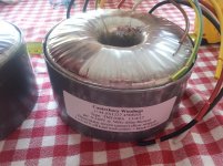
Woop - the post arrived today with 2x transformers for the Q-Watt project. Should give 41V AC off load, and 39V AC @ 420 VA.
Thanks Delange, Kay.
Pops.
Woop - the post arrived today with 2x transformers for the Q-Watt project. Should give 41V AC off load, and 39V AC @ 420 VA.
Thanks Delange, Kay.
Pops.
Attachments
Popchops, just to mention in the Elektor Q-Watt article they state: -
2 x 40v, 500VA.
Their example was a Nuvotem Talema Tx as listed in RS Components, code 223-8285, £69.
What is the VA of the Canterbury Tx, just out of curiosity?
I'm sure the Canterbury quality will do its job.
Keep us posted
2 x 40v, 500VA.
Their example was a Nuvotem Talema Tx as listed in RS Components, code 223-8285, £69.
What is the VA of the Canterbury Tx, just out of curiosity?
I'm sure the Canterbury quality will do its job.
Keep us posted
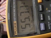
Bingo. Tranny is bang on target. My mains is normally really close to 240V and I'm getting 55-56V DC.
Each transformer is built on a 500VA core but wound with more copper & lower flux density. Terry rates them at 420VA. Regulation is 'better than 5%'.
Pops.
Each transformer is built on a 500VA core but wound with more copper & lower flux density. Terry rates them at 420VA. Regulation is 'better than 5%'.
Pops.
Attachments
Last edited:
popchops, if you haven't done it, it'll be a good idea to check this out, taken from the Q-Watt article: -
Mount the plate to IC1 with enough distance from the PCB so it won’t come in contact with R1, R5 and R4.
Bend L1 a little (away) from the heat sink.
Important: the metal part of the backside of IC1 is connected to the negative supply voltage.
If only a thermal compound is used between heat sink and IC there is a big chance the heat sink is also connected to the negative supply voltage,.
Because of this i placed a piece of thermal insulator pad inbetween IC1 and its heatsink, so that the metal part on rear side of IC1 was completely covered, and therefore the high possibility of the heatsink being at -55v was removed.
These are wound for 230V primary so 40V version is closer to 42V with 240V input.Popchops, just to mention in the Elektor Q-Watt article they state: -
2 x 40v, 500VA.
Their example was a Nuvotem Talema Tx as listed in RS Components, code 223-8285
And the 40V rating is at full load so actually you would get 45V AC at idle in the UK. You really want 41V AC at idle.
Last edited:
One Q-Watt (dual channel) up and working! 😎
No issues at all of stability nor oscillation in any shape or form! 😎
My life and my Q-Watt project were in my hands when i begun this project, I'm still alive and my Q-Watt is working fantastic! 😉
Ive used the same case as fellow constructor popchops. A really good quality case.
The same Switched Mode Power Supplies SMPS500R's (S.M.P.S.) as fellow constructor delange. Quality products!
As popchops, i too am using the same case 3U 300mm deep case from hifi2000
https://www.modushop.biz/site/index.php?route=product/category&path=66_96
Take heed of Elektors write up about the setting up of the Q-Watt (i.e. 47R resistors etc.).
After the initial switch on (with working multimeter) the Quiescent current very comfortable settles down and was then adjusted to its 30mA. The Q-Watt was left on for 15/20 minutes and the Q.Current remained at 30mA.
Having run the Q-Watt for 15/20 minutes at quite a high volume, the heatsinks of the 3U case remained quite cool.
For those interested, attached is the PDF of the LME49811, that explains its 'onboard' protections. I used an insulator inbetween the IC and the heatsink, thus removing the -55v on its heatsink.
In post #26 there is information of the thermal characteristics of the 3U case.
Post #35 explains about a better pot to adjust the Q.Current, i have these fitted.
Post #48 is an explanation for those using a S.M.P.S. so that the Q-Watt relay is switched on. Designed by 'delange', I too used this Cct.
Post #101 (and #104/146) delange explains the use of an input level pot, which i found to be an excellent idea and i too have implemented it.
I preferred to use M3 nylon standoffs for the PCB's and SMPS's.
Finally, i repeat myself to pass on my thanks to 'delange' for all his help and guidance from day one, its really great that people who have also constructed the Q-Watt go out of their way to help other constructors. 🙂
One Q-Watt (dual channel) up and working! 😎
No issues at all of stability nor oscillation in any shape or form! 😎
My life and my Q-Watt project were in my hands when i begun this project, I'm still alive and my Q-Watt is working fantastic! 😉
Great news. Good job. Now I need to get a shift on.
Pops.
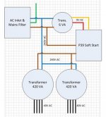
I tested the ESP P39 soft start with both transformers (2x 420VA). Starts up fine with 3.15A slo-blo fuse. P39 was modified slightly to use 33R for inrush current limiting (3x 100R 10W). Mains current is limited to 10A for approx 0.1 seconds, shared between the two PS channels.
Temperature of the three current limiting resistors increases by 1.5 deg C each start. Takes about 90s to cool.
Will try 3A fuse and 2.5A fuse later.
Pops.
Temperature of the three current limiting resistors increases by 1.5 deg C each start. Takes about 90s to cool.
Will try 3A fuse and 2.5A fuse later.
Pops.
Last edited:
Good luck popchops, slowly but surely is best.
Just need to sort out the screws and anodised top and bottom covers on the screw holes.
My 99% project pictures I'll post on Monday.
My audio tests were done with a small pair of 150w JBL speakers.
Audio sources tested were with several audio tracks on pop, jazz and classical music, downloaded as Flac. Quality was superb!
Elektor Q-Watt amplifier
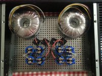
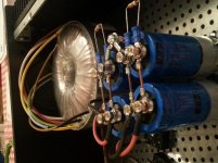
My Q-Watt (dual channel) 98% completed.
With no issues at all of stability nor oscillation in any shape, form or colour!
Thankfully my life and my Q-Watt project were in my hands when the project began, I'm still alive and my Q-Watt is working fantastic!
Just top and bottom plates, plus the feet remain to be fitted, and then some labelling.
Attachments
![20170424_090133[1].jpg](/community/data/attachments/562/562081-125af572c12682ae826da1665b523e04.jpg?hash=Elr1csEmgq)
![20170424_090119[1].jpg](/community/data/attachments/562/562064-03cb03408ec030b1de9958147bd5fef9.jpg?hash=A8sDQI7AML)
![20170424_090524[1].jpg](/community/data/attachments/562/562100-1ce5e02a9856cd3f3322a230fd9079c5.jpg?hash=HOXgKphWzT)
Last edited:
Delange, a query with regards to the 'power on' led you previously mentioned.
As you have the same SMPS's from where have you taken the supply for the front led?
Thanks
The power LED is a warm white and I’m using a 10k resistor to limit the current and therefore the brightness as well. I don’t want the LED to be too bright…
You could do it like this (see image on post #125):
* drill a 1,5 mm hole all the way through the front panel
* from the back of the panel, drill a 3 mm hole (for a 3 mm LED) about 4 or 5 mm deep
* insert the LED from the back
* use hot glue, at the back, to hold the LED in place.
The result is a tiny hole in the front from where the light will emit. Use a quite high resistor in front of the LED to limit the current (and light). You don't want the LED to bright. Personally I like a white LED]
As you have the same SMPS's from where have you taken the supply for the front led?
Thanks
Delange, a query with regards to the 'power on' led you previously mentioned.
As you have the same SMPS's from where have you taken the supply for the front led?
Thanks
I use the - (minus) 16 volts aux supply for the power LED.
You could also connect the power LED (in series with the 10k resistor) to the FET that switch the opto-coupler LED. The advantage of this is that the power LED will go off a lot faster when you switch off the amp. The aux supply seem to have quite large buffer caps. Since the power LEd in series with a 10k resistor doesn't draw a lot of current, it takes a while before it goes off when connected to the - 16 volts directly.
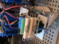
Hi popchops. The pcb with the 3 x 100R, 10W resistors is the soft start circuit?
If that's the case it's only being used, and only operates on switch on, acting as 'Soft Start?
Just a little concerned by the possible heat, over time, from the 10W resistors, in the way they are mounted, one under the other.
What about mounting the pcb so that the 10W's are horizontal, allowing the heat from each one to rise without heating the others too much?
Hi Calpe. Yep the 3x 100R resistors form a 33R current limiter that is switched in for about 0.1 seconds.
It seems to be quite reliable. If it works, the temp rise in each resistor is <2 deg C (per start). If the relay fails open then no amount of cooling airflow will save them. Still protects the amp though. At the end of the day the whole soft start is quite cheap and replaceable.
Just need to keep the resistors away from costly or flammable components in case of meltdown.
Pops.
Hi Calpe. Yep the 3x 100R resistors form a 33R current limiter that is switched in for about 0.1 seconds.
It seems to be quite reliable. If it works, the temp rise in each resistor is <2 deg C (per start). If the relay fails open then no amount of cooling airflow will save them. Still protects the amp though. At the end of the day the whole soft start is quite cheap and replaceable.
Just need to keep the resistors away from costly or flammable components in case of meltdown.
Pops.
If space is a concern, you could always use one 50 watt resistor. These are encased in a heatsink(like then one in the enclosed picture).
I recently repaired an old Nikko Alpha VI and used these. Since the are encased I mounted them against the enclosure.
Attachments

Hi popchops. The pcb with the 3 x 100R, 10W resistors is the soft start circuit?
If that's the case it's only being used, and only operates on switch on, acting as 'Soft Start?
Just a little concerned by the possible heat, over time, from the 10W resistors, in the way they are mounted, one under the other.
What about mounting the pcb so that the 10W's are horizontal, allowing the heat from each one to rise without heating the others too much?
Hi Calpe. Yep the 3x 100R resistors form a 33R current limiter that is switched in for about 0.1 seconds.
It seems to be quite reliable. If it works, the temp rise in each resistor is <2 deg C (per start). If the relay fails open then no amount of cooling airflow will save them. Still protects the amp though. At the end of the day the whole soft start is quite cheap and replaceable.
Just need to keep the resistors away from costly or flammable components in case of meltdown.
Pops.
When the delayed bypass relay triggers, the resistors are shorted. They then have no voltage across them. But they are still at LIVE mains voltage. Those exposed wires are a danger.If space is a concern, you could always use one 50 watt resistor. These are encased in a heatsink(like then one in the enclosed picture).
I recently repaired an old Nikko Alpha VI and used these. Since the are encased I mounted them against the enclosure.
If the bypass relay fails to trigger and the soft start resistors are left in circuit, then the heating effect can be enormous.
P=230Vac*230Vac/33r33 = 1587Watts initially.
No wire wound, whether encased in aluminium, or otherwise can survive this for long.
Although I choose to use fixed series connected Power Resistors, I do recommend Power Thermistors (series connected if need be), since these will survive a lazy, or non operating bypass relay.
Back to those exposed wires:
Axially leaded power resistors will need some form of insulated protection (cage) from dropped tools, or stray fingers.
A radial Power Resistor with both leads coming out from the end and passing straight through the PCB leaves no exposed LIVE wires on the top side of the PCB. Only the bottom side needs some tools protection. A sheet of robust plastic film attached under the PCB can achieve a lot.
Last edited:
Thanks all. I do have a 75W 47R resistor but itwould still be destroyed in case of relay failure and would probably absorb a great deal more energy first. Separate resistors cool faster.
I will have a think about a plastic tub to put over the soft start.
Pops.
I will have a think about a plastic tub to put over the soft start.
Pops.
- Home
- Amplifiers
- Chip Amps
- My Q-Watt project